www.miinet.comMoore Industries-International, Inc.
- 67 -
User’s Manual
225-748-00P
August 2024
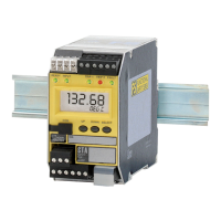
Programmable RTD, T/C, Ohms, mV and Potentiometer Safety Trip Alarm
STA
TPRG
SECTION 7
Operation and Maintenance
Proof Test Procedure
It is normal practice with SIS that the components undergo periodic proof tests to expose
dangerous faults that are not detected by internal diagnostic tests. Calculation of the required
proof test interval can be made using data in the FMEDA report (Moore Industries’ Document
No: 700-702-32). Periodically testing the STA using the proof test steps outlined below, the
accumulated PFDAVG value can be reduced to a smaller but nonzero¹ value.
The proof test shall cover the following functionality:
• Isolation and grounding
• Input accuracy within 2%
• Relay function
• Analog Output accuracy within 2% (if used)
The proof test below is provided as an example covering safety functionality for an STA. When
using the product in a safety function, the proof test should be tailored to the specic STA type
and conguration since any faults related to unused features/congurations will not aect the
safety function. It is the responsibility of the end user to dene the specic proof test and proof
test interval for their applications.
Note: ¹ Nonzero value = 4.38 FITs (97% Proof Test coverage)
Equipment Required
• Variable Input Source RTD/Resistance or Thermocouple/mV Accurate to +/-0.2% of span
• Power Supply set to nominal voltage (eg. 24VDC)
• Multimeter with an accuracy of 0.2%
• Load resistor 250Ω 1/4W 0.1%
STA TPRG (RTD, Thermocouple, Ohms, Potentiometer and mV type inputs) Proof Test
STA Configuration:
Thermocouple Type J input 0-100
o
C range; 4-20mA Analog Output, Fail Low; NO (Normally
Open) relay contacts used for the Fault and Trip Alarms; TRIP1 set High @ 80
o
C; TRIP2 set Low
@ 30
o
C ; Input FAULTS set non-latching.