www.miinet.com Moore Industries-International, Inc.
- 68 -
User’s Manual
225-748-00P
August 2024
Programmable RTD, T/C, Ohms, mV and Potentiometer Safety Trip Alarm
STA
TPRG
SECTION 7
Steps:
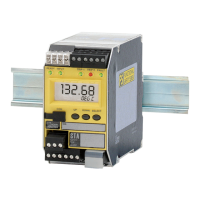
1. Disconnect all wires from the unit. Check that the resistance between the case and all
terminals is >1MΩ except the GND pin which = 0Ω
2. Connect input mV source and AO (Analog Output) per hookup diagram using a 250ohm
resistor as output load.
3. Connect power to the STA.
4. Set the input value to 0
o
C, 50
o
C and 100
o
C and verify the following at each input level:
INPUT Display AO TRIP1 (NO) TRIP2 (NO) FAULT
(NO)
0
o
C
-0.02-0.02C 0.98-1.02V 0Ω >1 MΩ 0Ω
50
o
C
49-51C 2.94-3.06V 0Ω 0Ω 0Ω
100
o
C
98-102C 4.9-5.1V >1 MΩ 0Ω 0Ω
Note: Measure the resistance across Normally Open contacts to verify TRIP and FAULT state.
5. To test Broken Wire diagnostic, remove mV source and verify the following²:
INPUT Display AO FAULT (NO)
Disconnected WIRES BROKE 0.86-0.92V >1 MΩ
6. Disconnect the AO load resistor and reconnect the STA to the safety system.
Note: ² For RTD input, remove and reconnect each wire in turn to verify the diagnostic for each
connection.
SELECT
DOWN
UP
COM
READY
INPUT TRIP 1TRIP 2
FAULT
STA
SAFETY
TRIP
ALARM
TAG
ohmmeter
-
+
-
+
Thermocouple
or mV Source
-
+
VOLTMETER
250
Ω
AC OR DC
POWER
SUPPLY
GND
-
+
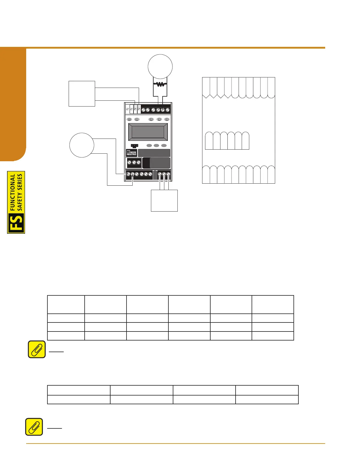
Terminal Key
GND
ACC/DCC
AC/DC
Not Used
NC2
CM2
NO2
NC1
CM1
NO1
N/A
N/A
N/A
NC3
CM3
NO3
TC+
TC-
MR
MR
+Io Source
-Io Source
+Io Sink
+Vo
-Vo
-Io Sink
1 2 3
4