www.miinet.comMoore Industries-International, Inc.
- 65 -
User’s Manual
225-748-00P
August 2024
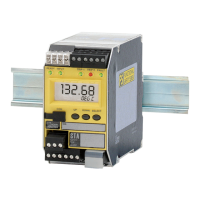
Programmable RTD, T/C, Ohms, mV and Potentiometer Safety Trip Alarm
STA
TPRG
SECTION 7
Configuration
The unit can be congured using the front panel buttons or PC Conguration Software as
described in this manual.
Note: While the system is in conguration mode the system is in an oine mode and is not
performing the safety function.
Do not attempt to connect the STA Communications Cable to the STA while the output relays are
connected to a load.
After making any conguration changes, the user must validate the operation of the STA oine to
ensure that the changes work safely, prior to putting it back into operation.
The following considerations and restrictions will apply when using the STA in a safety
application:
Trip Relay used as safety output: One or both trip alarms must be connected to the actuator/
equipment under control (EUC). The separate dedicated fault relay must either be
connected in series with the trip alarm OR connected to a separate indicator to only alarm
the fault while maintaining the process in normal operation. Refer to Figures 8.1 and 8.2 in
Section 8 for typical STA configurations.
Analog Output (AO) used as safety output: The STA may optionally be provided with an
analog output (AO) which can be used for connecting to displays, control systems, etc.
For STA units with V1.2 rmware or less, the AO is NOT certied for safety use and must not be
used as any part of a safety loop. The analog circuit is isolated from the STA safety circuits and
consequently its failure will not compromise the certied safety function of the STA.
For STA units with V1.3 rmware or later, the AO is certied for safety use and can be used in the
safety path. Refer to Figures 8.4 and 8.5 in Section 8 for typical congurations.
The AO must be configured as follows: The AO is a current output set at 4 to 20mA. The AO
is set to fail low (fail high is a non fail-safe condition when power is lost). The logic solver
is either configured to detect a ‘fail low’ condition for SIL1 applications (anything less than
4.0mA is detected as a fault) or a `fail windowed’ condition for SIL2 applications (anything
outside the 4-20mA range is detected as a fault). The fault alarm relay is used by the logic
solver to detect failures.
Note: When conguring Out of Range for STA units with rmware V1.5 or later, the Out of
Range value must be congured for 2% or less (default setting is 1%).
High Availability Configuration
(Figures 8.1 & 8.2)
Separating the process and fault loads increases availability but its use must be authorized only
after a careful hazard and operability study involving suitably qualied persons.
Warning: With this conguration, an internal STA fault would not trip the EUC.
Sensor Types
The STA is designed for use with a wide variety of inputs. It is the end user’s responsibility to
ensure that the chosen sensor is capable of achieving the required loop SIL.