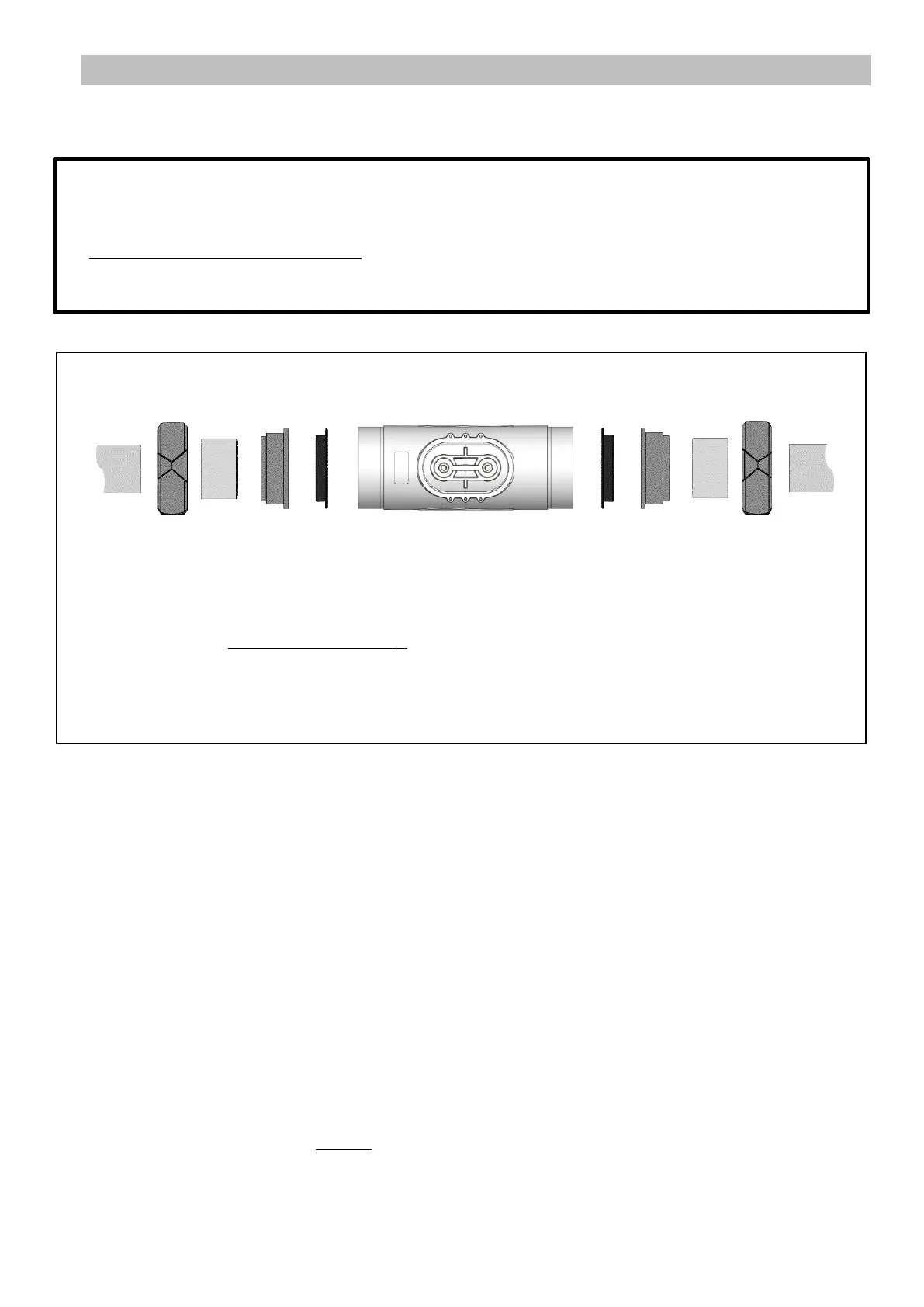
Exploded diagram of the assembly:
A: Pipe
B: Nut (x2)
C: Reducer (x2) (only to be fitted if pipe A has an outer diameter of 1’’5)
D: Collar (x2) (2’’)
E: Seal (x2)
F: Cell
1) If pipe A has an outer diameter of 2’’, cut the pipe to a length of 236mm/9’’3.
If pipe A has an outer diameter of 1’’5, cut the pipe on a length to be adapted according to the chosen reducer.
2) Fully disassemble the cell as per the exploded diagram above.
3) Rub down all bonding surfaces with sand paper: pipes A, reducers C (not included, if needed), collars D.
4) Slide each nut B onto each pipe A (pay attention to the direction).
5) Glue together each unit comprising [pipe A - reducer C (if needed) - collar D].
6) Wait for the glue to dry completely.
7) Grease each seal E.
8) Place each seal E inside each collar D.
9) Screw on and tighten the 2 nuts B by hand onto cell F.
I
• The reducers mentioned in this chapter may or may not be supplied depending on the cell model.
• The electrical connections at cell level:
- must not be oriented upwards in order to avoid any deposit of water or moisture on them.
- must be sufficiently and regularly (re)tightened using an appropriate wrench