6881094C31-E November 16, 2006
Troubleshooting Charts: VCO TX/RX Unlock 5-23
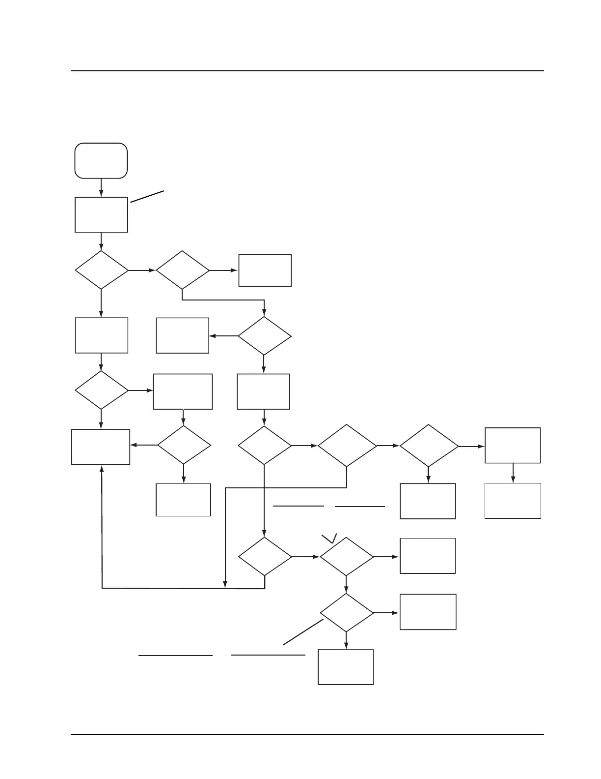
5.11 VCO TX/RX Unlock
MAEPF-27398-B
VCO TX/RX
unlock
<0.6Vdc
>11.0Vdc or
drifting?
3V at TP5?
Yes
Yes
Yes
Yes
Yes
Yes
No
No
No No
No
Yes
Yes
Yes
Frequency
detected?
VCO locked?
No
Yes
No
5V at TP3?
Check
VOCON board
Check parts
around BJT. If
OK, replace BJT
Check control
voltage at
TP243
Check parts
around U1. If
OK, replace U2
Aux.
line 1 (2, 3, 4)
is high?
Aux. line
3 high for TX
or low for RX
(VHF)?
Is unit
VHF?
No
No
FET
drain voltage
0V?
Check parts
around FET. If
OK, replace FET
No
BJT
emitter voltage
>1.2V?
Check parts
around U300. If
OK, replace U300
Yes
Check parts
around U302.
If OK, replace
Q302
No
Is pin
19 of VCOBIC
low for RX and
4.5 for TX?
Remove
VCO buffer
shield (SH302)
Check parts
around Q301. I
OK, replace Q30
Check parts
around U2. If
OK, replace U2
Remove
VCO shield
Check parts
around U202. If
OK, replace U202
"Sniff"
frequency near
VCO shield
Check if VCO
is locked using
spectrum analyzer
Sniff: Using an inductive field probe
as an antenna to measure
frequency. Place the probe
approximately 1/2 inch away
from components to be sniffed.
Q302 VC01
Q306 VC02
Q309 VC03
Field Effect
Transistor (FET)
Q301 VC01
Q303 VC02
Q308 VC03
Bi-polar Transistor (BJT)
Bi-polar Transistor (BJT)
Q302 RX1
Q301 RX2
Q304 TX
Field Effect
Transistor (FET)
Q306 RX1 Aux 2
Q305 RX2 Aux 3
Q308 TX Aux 4

 Loading...


