November 16, 2006 6881094C31-E
2-4 Radio Power: DC Power Routing—Transceiver Board
2.2 DC Power Routing—Transceiver Board
NOTE: Refer to Table 8-1, “List of Transceiver Schematics and Board Overlays,” on page 8-1 for a
listing of schematics showing the transceiver board DC power routing components.
Connector J1, the B-plus assembly, connects the battery to the transceiver board. Capacitors C1,
C2, and C3 provide protection against momentary breaks at the B-plus connector due to contact
bounce when the radio is dropped.
UHF R1 and 700–800 MHz: Components C5, E4, C7, and E1 form a power-line filter for signal
RAWB+, which supplies battery voltage to the transmitter PA.
UHF R2 and VHF: Component E1 forms a power-line filter for signal RAWB+, which supplies battery
voltage to the transmitter PA.
Transistor Q1, controlled by signal SWB+ (SB+ for VHF) from the VOCON board, turns on XB+,
which supplies to the 5-V linear regulator and TX_ALC block.
Fuse F901 and filter C11, L1, C10 (C14, L1, C13 for VHF) supply fused B-plus to the VOCON board.
In turn, the VOCON board supplies VSW1, regulated 3.8 Vdc, from the Global Control Audio and
Power (GCAP) switching regulator to the XCVR. Switch Q99 (Q503 for VHF), controlled by SWB+,
turns on V38 to the XCVR 3-V linear regulators. For kit NNTN5567, the Vocon board supplies VSW1,
regulated 3.6Vdc, from the Mako switching regulator to the XCVR. The XCVR regulated power
supplies are summarized in Table 2-3.
2.3 DC Power Routing—VOCON Board
NOTE: Refer to Table 8-2, “List of VOCON Schematics and Board Overlays,” on page 8-1 for a listing
of schematics showing the VOCON board DC power routing components.
Raw B+, or unswitched B+, (UNSW_B+) is routed to connector P1 on the transceiver board, and
then on to P201 on the VOCON board. Here the UNSW B+ is forwarded to the radio’s control top
On/Off/volume knob through connector J101 and a flex circuit, as well as to regulator U505 (VCC5).
The On/Off/volume knob controls B+SENSE to Q502, which in turn controls Q501. Transistor Q501
is a solid-state power switch that provides SW B+ to the VOCON board, the audio PA, the GCAP II
IC (via GCAP_B+), and back to the transceiver board. In NNTN5567, the control signal, FET_ENX,
for the power MOSFET is generated by the MAKO IC upon applying B+ sense to the BJT switch. The
MOSFET provides SW B+ to the VOCON board, MAKO IC, audio power amplifier, and transceiver
board.
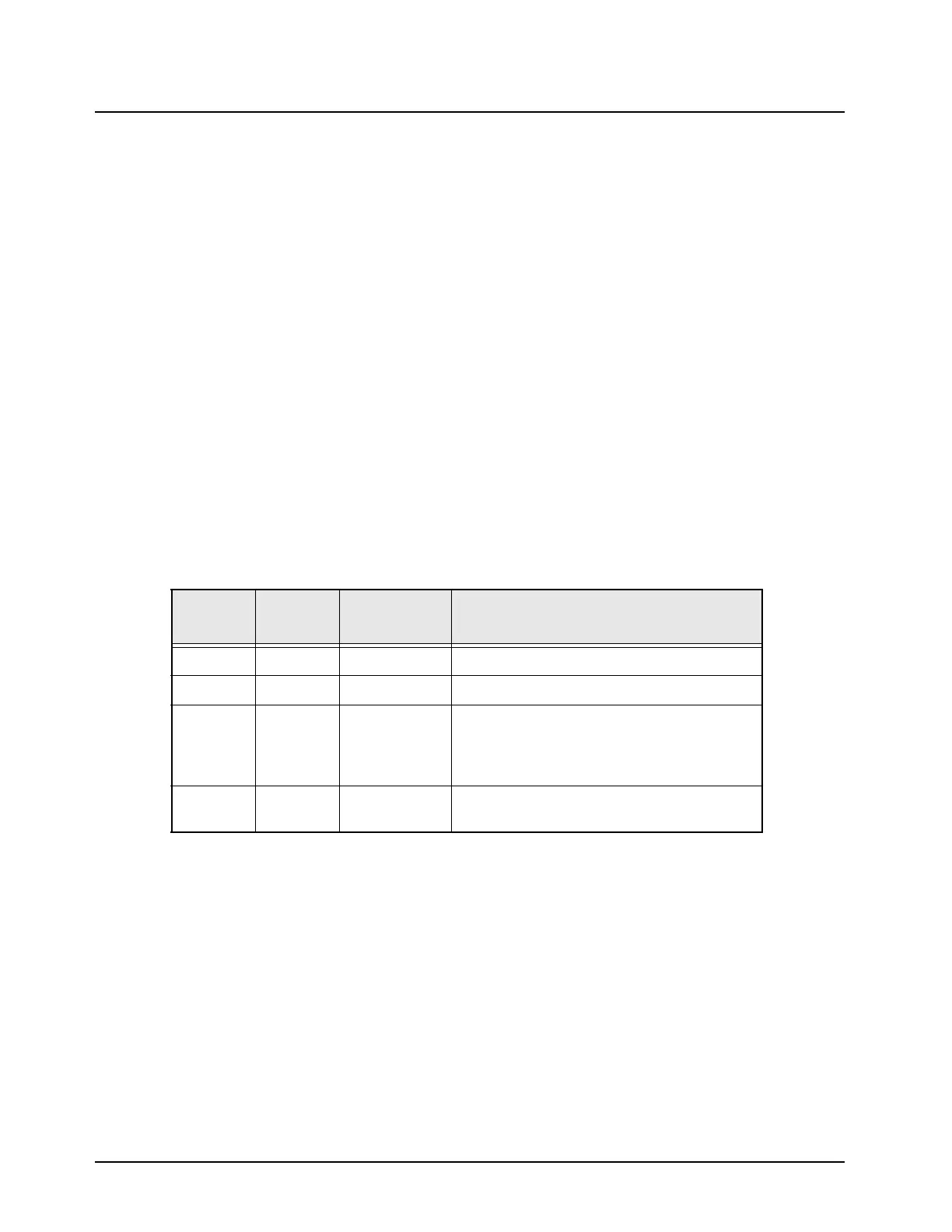
Table 2-3. Transceiver Voltage Regulators
Ref.
Desig.
IC
Name
Output
Signal Name
Description
U1 LP2989 V5A Regulated 5.0 Vdc
U2 LP3985 V3D Regulated 3.0 Vdc digital
U3 LP3985 V3A UHF R1 and 700–800 MHz: Regulated 3.0 Vdc
analog for the RX FE
UHF R2 and VHF: Regulated 3.0 Vdc analog
for synthesizer
U5 LP3985 V3B
UHF R2 and VHF only: Regulated 3.0 Vdc
miscellaneous supply

 Loading...


