November 16, 2006 6881094C31-E
3-16 Theory of Operation: VOCON Board
Transistors Q307 and Q310 form a 3.3 Vdc-to-5 Vdc logic-level shifter for the signal from the FracN
AUX3 pin to the VCOBIC.
3.2 VOCON Board
This section provides a detailed circuit description of the ASTRO XTS 5000 VOCON board.
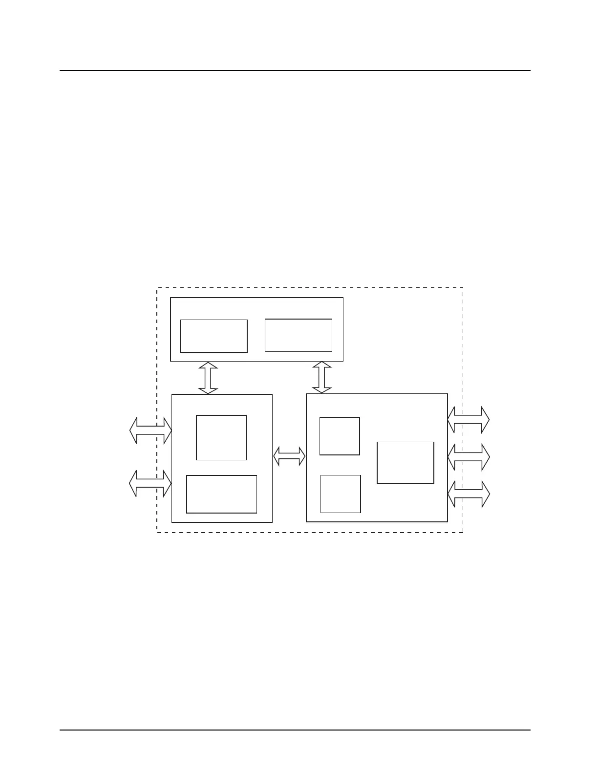
The VOCON board (Figure 3-7 and Figure 3-8) is divided into the following sections:
• Controller and Memory
• Audio and Power
• Interface Support
3.2.1 Interconnections
The VOCON board interconnection diagram (see Figure 3-7 and Figure 3-8) contains three
functional blocks and five connector symbols.
Figure 3-7. VOCON Board Interconnections
SRAM
1MByte
INTERFACE SUPPORT
ESD Protection and
Side Connector
Circuitry
ASIC
Clocks and Side
Connector Support
VOCON
Board
CONTROLLER AND MEMORY
FLASH
8MBytes
Dual-Core
Processor
MCU and DSP
Keypad
22 pins
Display
22 pins
Encryption
40 pins
AUDIO AND POWER
Audio
EEPOT
Pre-amp and
Power Amp
GCAP II
and Discrete
Voltage Regulators
RF
26 pins
Universal
40 pins
MAEPF-27413-A

 Loading...


