6881094C31-E November 16, 2006
Theory of Operation: Transceiver Board 3-5
3.1.1.3 Antenna Port J2
Antenna port J2 is a surface-mount, miniature coaxial connector for the antenna cable.
3.1.1.4 Serial EEPROM
The serial, electrostatically erasable, programmable, read-only memory (EEPROM), U907 in VHF
and 700–800 MHz or U4 in UHF Range 1, holds all of the transceiver tuning data. This allows
transceivers to be tuned in the factory and installed in the field without retuning.
3.1.1.5 Power Conditioning Components
DC power-conditioning components include zener diodes, capacitors, ferrite beads, a power
inductor, and the fuse. Diodes VR1 and VR2 provide over-voltage protection. Ferrite beads
(designated E1, etc.) and capacitors suppress electromagnetic interference from the transceiver.
The power-line filter consisting of L1, C13, and C14 for VHF radios or L1, C10, and C11 for UHF
Range 1 and 700–800 MHz radios, suppresses digital noise from the VOCON board switching
power supplies that could degrade the transmitter spectral purity.
Pass transistor Q1 switches the battery voltage to the transceiver when control signal SWB+ or SB+
from the VOCON board is asserted high. This increases the transceiver’s immunity to conducted
interference that might be present on SWB+ or SB+, such as from switching voltage regulators on
the VOCON board.
Ground clips G1 through G12 make contact between the transceiver board ground and the radio
chassis. The chassis connection is a necessary electrical reference point to complete the antenna
circuit path. Shields SH101 through SH700 and the tool hole appear on the schematic to show their
connection to ground.
3.1.2 Receiver
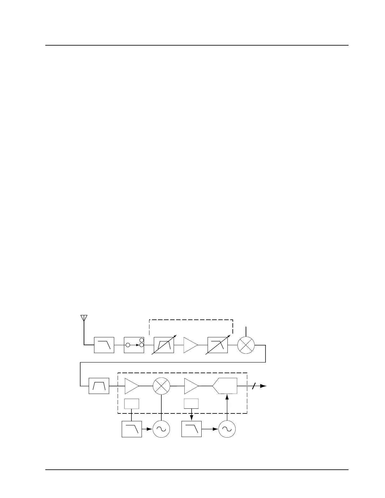
The XTS 5000 transceiver has a dual-conversion superheterodyne receiver. Figure 3-4 illustrates
the major receiver components:
• Receiver Front End
• Receiver Back End
Figure 3-4. Receiver Block Diagram
RF Input
RX Front End
Harmonic
Filter
ADC
LO
CKO
RX_SSI_ DATA
to VOCON Board
XTAL
Filter
ABACUS III - RX Back End
Antenna
Switch
LNA
Tuneable
Preselector
Filter
Tuneable
Preselector
Filter
1st
Mixer
1st LO
3
MAEPF-27278-A

 Loading...


