Chapter 7 Troubleshooting Tables
7.1 List of Board and IC Signals
Due to the nature of the schematic-generating program, signal names might be different when they
are not directly connected to the same point. The tables in this chapter provide a cross reference to
the various pinouts for these signals. Table 7-1 lists and provides links to each of the tables in this
chapter.
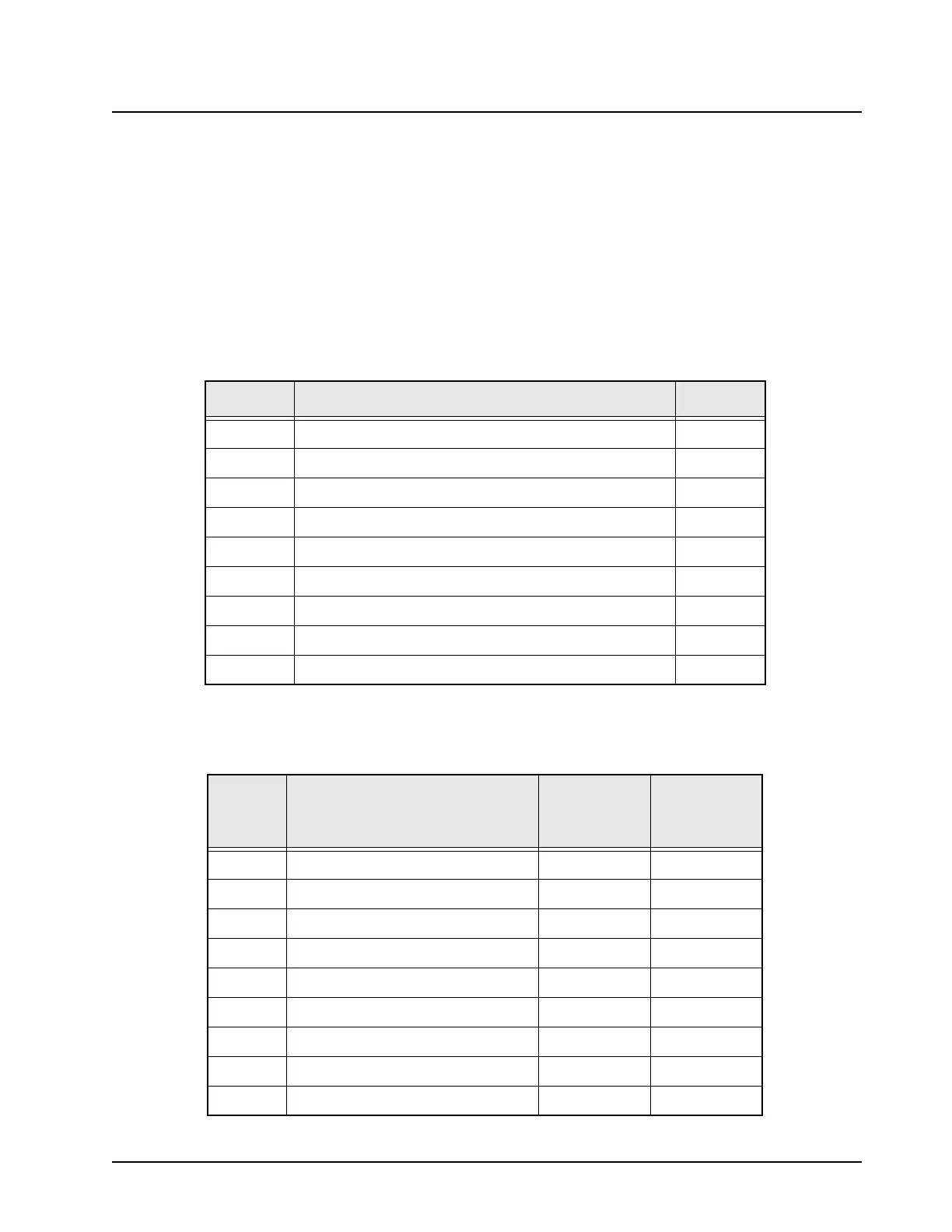
Table 7-1. List of Tables of Board and IC Signals
Table No. Table Name Page No.
7-2 J101 VOCON Board to Controls Flex Assembly 7-1
7-3 J107 VOCON Board to Keypad Module 7-3
7-4 J701 VOCON Board to Encryption Module 7-4
7-5 U402 FLASH Pinouts 7-5
7-6 U403 SRAM Pinouts 7-7
7-7 U401 Patriot MCU/DSP IC Pinouts 7-9
7-8 U301 Flipper IC Pinouts 7-18
7-9 U501 GCAP II IC Pinouts 7-20
7-10 U501 MAKO IC Pinouts (for kit NNTN5567) 7-24
Table 7-2. J101 VOCON Board to Controls Flex Assembly
J101
Pin No.
Description To/From
Side
Connector
Number
1 UC_CTS TP208 10
2 UC_LHDATA_KEYFAIL TP206 13
3 DGND03 TP202 8
4 UC_RS232DIN_USB- R253 12
5 UC_EXT_SPKR_NEG- TP213 6
6 UC_RS232DOUT_USB+ R252 11
7 UC_OPT_SEL2 R218 5
8 UC_SB9600_BUSY TP207 9
9 UC_EXT_SKPR TP212 2

 Loading...


