November 16, 2006 6881094C31-E
3-2 Theory of Operation: Transceiver Board
Figure 3-1. XTS 5000 Overall Block Diagram
3.1 Transceiver Board
The transceiver (XCVR) board performs the transmitter and receiver functions necessary to translate
between voice and data from the VOCON board and the modulated radio-frequency (RF) carrier at
the antenna. The transceiver board contains all the radio’s RF circuits for the following major
components:
• Receiver
• Transmitter
• Frequency Generation Unit (FGU)
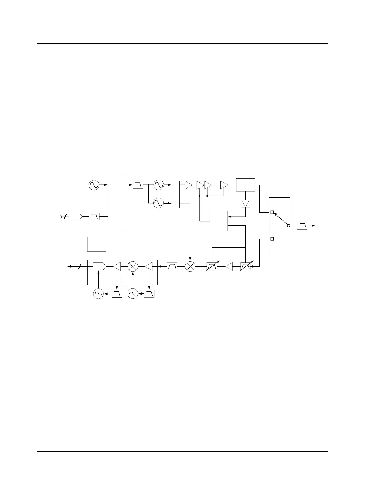
Figure 3-2 illustrates the VHF transceiver board block diagram while Figure 3-3 on page 3-3
illustrates the transceiver UHF Range 1 and 700–800 MHz transceiver block diagrams.
Figure 3-2. Transceiver (VHF) Block Diagram (Power and Control Omitted)
Reference
Oscillator
FracN
U203
MOD
IN
Loop
Filter
LPF
FL200
EPIC
Y200
DAC
U203
VCO
VCOBIC
U202
VCO
Crystal
Filter
FL403
Mixer
U401
2ND
LO
Sample
Clk
RX_SSI to
VOCON Board
TX_SSI from
VOCON Board
Preselector
Filter
FL401
PCIC
U104
Power
Module
TX
Buffer
Q304
TX Driver
Amplifier
U102
RF Power
Detector
D103
Directional
Coupler
U101
Antenna
Switch
Preselector
Filter
FL402
RX LNA
Q401
To
Antenna
Harmonic
Filter
Serial EE
PROM
U4
ABACUS III U500
MAEPF-27529-O
3
3

 Loading...


