6881094C31-E November 16, 2006
Troubleshooting Charts: RX RF 5-31
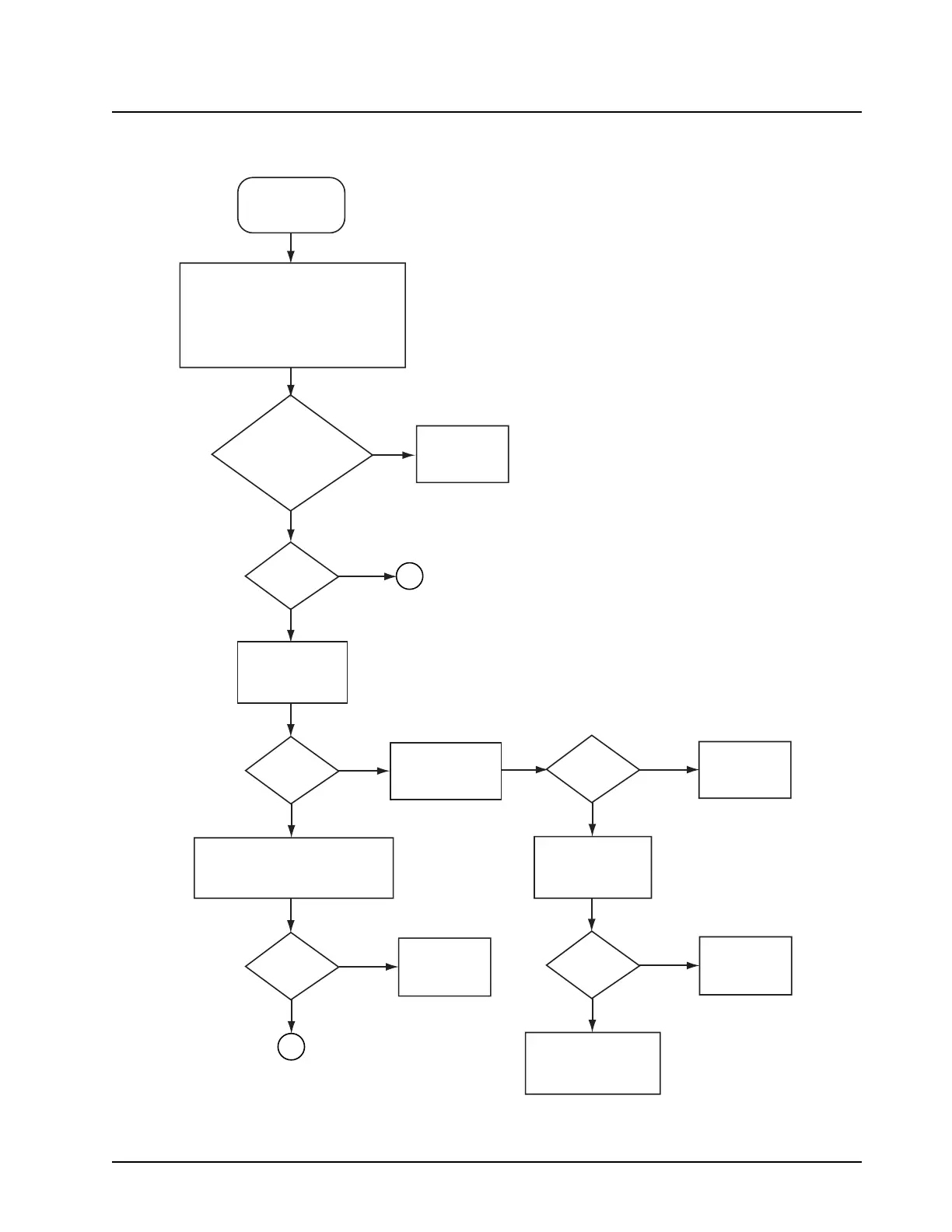
5.14 RX RF—Page 1
Frequency OK?
VHF: 44.85 MHz
UHF R1/R2: 73.35 MHz
700-800: 109.65 MHz
Inject a standard FM test signal into the
antenna port. Use CPS to ensure that
attenuator feature is disabled. Use a
spectrum analyzer and high-impedance
RF probe to measure the IF signal
at TP12 (700-800) or
TP15 (VHF) or TP455 (UHF R2) on side 2
No
No
Yes
Yes
Poor RX
sensitivity or
no RX audio
Check
RXLO
Replace
bad part
Remove cable
assembly, measure
insertion loss
Visual
inspection
OK?
No
Yes
Bad antenna connector.
Replace chassis
(connector is not
serviceable)
Loss
< 0.2 db?
Replace
cable assembl
No
Yes
Inspect coaxial
antenna connector
and cable assembly
Measure RF
input level
at TP02
Measure RF levels at TP02 and
TP13 (UHF Range 1 & 700-800)
or TP401 (VHF or UHF Range 2),
compute SW_FL loss
RF level
about
-47 dBm?
No
Yes
SW_FL
loss < 2 dB?
Check
SW_FL
Yes
No
IF
level about
-38 dBm?
1
2
3 kHz FM deviation,
1 kHz rate, -47 dBm
MAEPF-27470-C

 Loading...


