10-4 M68000 8-/16-/32-BIT MICROPROCESSORS USER'S MANUAL MOTOROLA
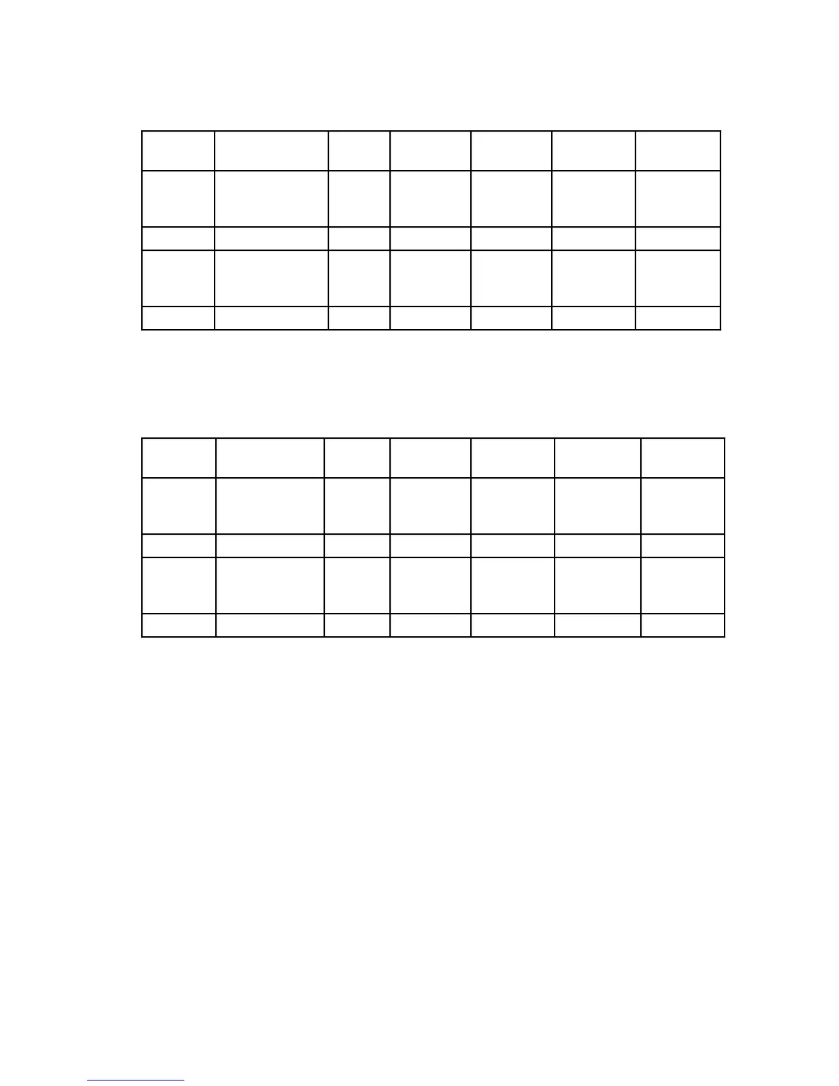
Table 10-1. Power Dissipation and Junction Temperature vs Temperature
(θJ
C
=θJ
A
)
Package T
A
Range
θ
J
C
(°C/W)
P
D
(W)
@ T
A
Min.
T
J
(°C)
@ T
A
Min.
P
D
(W)
@ T
A
Max.
T
J
(°C)
@ T
A
Max.
L/LC 0°C to 70°C
-40°C to 85°C
0°C to 85°C
15
15
15
1.5
1.7
1.5
23
-14
23
1.2
1.2
1.2
88
103
103
P0°C to 70°C 15 1.5 23 1.2 88
R/RC 0°C to 70°C
-40°C to 85°C
0°C to 85°C
15
15
15
1.5
1.7
1.5
23
-14
23
1.2
1.2
1.2
88
103
103
FN 0° C to 70°C 25 1.5 38 1.2 101
NOTE: Table does not include values for the MC68000 12F.
Does not apply to the MC68HC000, MC68HC001, and MC68EC000.
Table 10-2. Power Dissipation and Junction Temperature vs Temperature
(
θ
J
C
≠
θ
J
C
)
Package T
A
Range
θ
J
A
(°C/W)
P
D
(W)
@ T
A
Min.
T
J
(°C)
@ T
A
Min.
P
D
(W)
@ T
A
Max.
T
J
(°C)
@ T
A
Max.
L/LC 0°C to 70°C
-40°C to 85°C
0°C to 85°C
30
30
30
1.5
1.7
1.5
23
-14
23
1.2
1.2
1.2
88
103
103
P0°C to 70°C 30 1.5 23 1.2 88
R/RC 0°C to 70°C
-40°C to 85°C
0°C to 85°C
33
33
33
1.5
1.7
1.5
23
-14
23
1.2
1.2
1.2
88
103
103
FN 0° C to 70°C 40 1.5 38 1.2 101
NOTE: Table does not include values for the MC68000 12F.
Does not apply to the MC68HC000, MC68HC001, and MC68EC000.
Values for thermal resistance presented in this manual, unless estimated, were derived
using the procedure described in Motorola Reliability Report 7843 “Thermal Resistance
Measurement Method for MC68XXX Microcomponent Devices”’ and are provided for
design purposes only. Thermal measurements are complex and dependent on procedure
and setup. User-derived values for thermal resistance may differ.
10.4 CMOS CONSIDERATIONS
The MC68HC000, MC68HC001, and MC68EC000, with it significantly lower power
consumption, has other considerations. The CMOS cell is basically composed of two
complementary transistors (a P channel and an N channel), and only one transistor is
turned on while the cell is in the steady state. The active P-channel transistor sources
current when the output is a logic high and presents a high impedance when the output is
logic low. Thus, the overall result is extremely low power consumption because no power
Frees
cale Semiconductor,
I
Freescale Semiconductor, Inc.
For More Information On This Product,
Go to: www.freescale.com
nc...
 Loading...

