MOTOROLA M68000 8-/16-/32-BIT MICROPROCESSORS USER'S MANUAL 10-13
6A
8
6
13
14
12
17
18
47
28
29
27
48
47
30
47
32
56
47
32
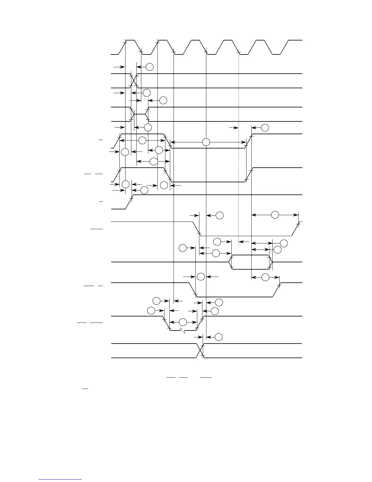
S0 S1 S2 S3 S4 S5 S6
CLK
FC2–FC0
A23–A0
AS
LDS / UDS
R/W
DTACK
DATA IN
BERR / BR
(NOTE 2)
HALT / RESET
47
ASYNCHRONOUS
INPUTS
(NOTE 1)
S7
31
7
11
11A
NOTES:
1. Setup time for the asynchronous inputs IPL2–IPL0 and AVEC (#47) guarantees their recognition at the
next falling edge of the clock.
2. BR need fall at this time only to insure being recognized at the end of the bus cycle.
3. Timing measurements are referenced to and from a low voltage of 0.8 V and a high voltage of 2.0 V,
unless otherwise noted. The voltage swing through this range should start outside and pass through the
range such that the rise or fall is linear between 0.8 V and 2.0 V.
9
15
29A
Figure 10-4. Read Cycle Timing Diagram
(Applies To All Processors Except The MC68EC000)
Frees
cale Semiconductor,
I
Freescale Semiconductor, Inc.
For More Information On This Product,
Go to: www.freescale.com
nc...
 Loading...

