ioLogik E1200 Series Using the Web Console
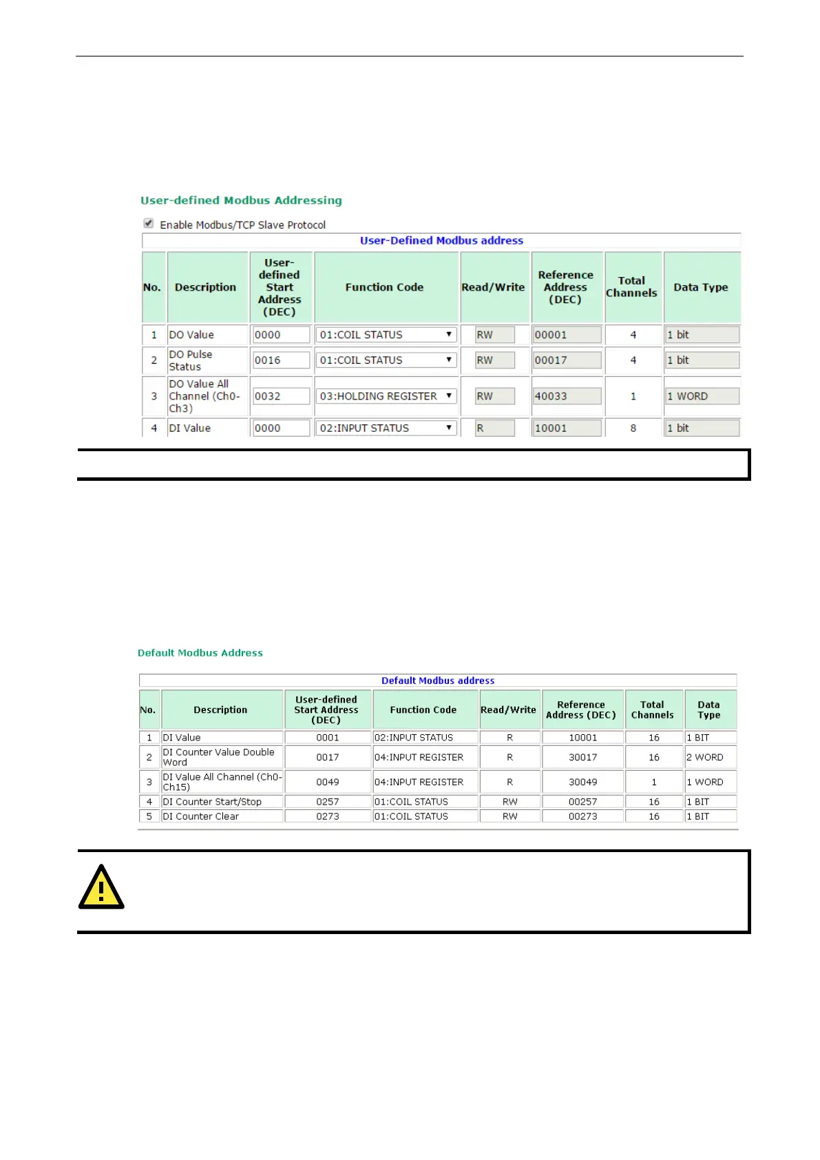
User-Defined Modbus Addressing
The input and output addresses can be configured on this page. Select the Enable Modbus/TCP Slave
Protocol checkbox, and then configure the start address of each Modbus function. If you do not want to use
the Modbus function, deselect the Enable Modbus/TCP Slave Protocol checkbox.
The maximum number of Modbus TCP master connection
s is 10.
Default Modbus Address
You can view the default Modbus address for all I/O devices on the Default Modbus Address settings page.
However, only the starting address will be displayed for each item with multiple reference addresses. For
example, if the reference addresses for DI Value start from 10001 and the second DI channel’s reference
address is 10002, only the first DI channel’s Modbus address of 10001 will be displayed. See the diagram
below.
ATTENTION
Disable the user
-defined Modbus addressing function if using the MXIO (.NET) library or MX-AOPC UA
Server
to control or monitor the ioLogik E1200’s I/O status.