6 Mounting
Maschinenfabrik Reinhausen GmbH 202340 4001150/12 ENMSENSE
®
DGA 2/3
To prepare the cable correctly, proceed as follows:
1. Open the device connection area. To do so, unscrew the 4captive screws
on the housing cover. The cover is connected to the device via hinges and
can be flipped open.
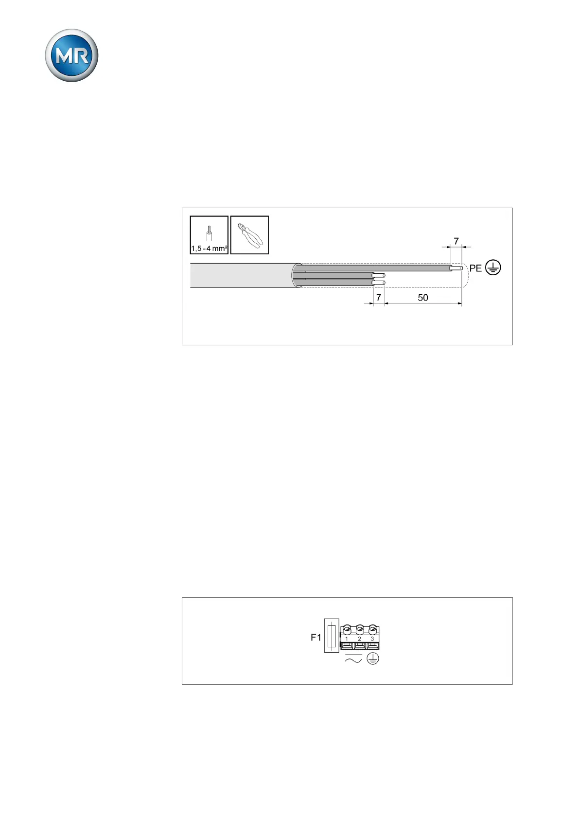
2. Remove the supply voltage cable jacket and cut the cable so that the
length of the PE wire is 50mm longer than the wires for L and N. Strip
7mm (1/4″) of the insulation from the wires and cap them off with ferrules.
Figure27: Preparing the cable
3. Remove the jacket from the cable for the relay and analog outputs. Strip
off 7mm (1/4“) of insulation from the wires and cap them off with ferrules.
4. Unscrew the required cable screw connections (M20x1.5).
5. Insert a sufficient length of cable through the cable gland and rubber gas-
ket and tighten the cable gland so that moisture cannot penetrate into the
connection area from outside.
6. Insert locking screws into the unused cable connections or replace the en-
tire cable connection with a locking screw so that the pass-through is wa-
tertight.
6.3.4 Supply voltage and protective conductor
To connect the cable for the supply voltage and the protective conductor,
proceed as follows:
1. Insert wire for the protective conductor into terminal3 (PE) and tighten the
screw terminal with 0.5Nm.
2. Insert wires for the supply voltage into terminal1 and terminal2 and
tighten the screw terminals with 0.5Nm.
Figure28: Supply voltage and protective ground connection
 Loading...