Do you have a question about the MSA FL500 and is the answer not in the manual?
Guidelines for the safe and proper installation and operation of the device.
Details on General Monitors' liability regarding product use and employer responsibility.
Specifies the warranty period and conditions for mechanical defects and faulty workmanship.
Defines the exclusive remedy for warranty breaches, typically repair or replacement.
Excludes liability for economic, special, incidental, or consequential damages.
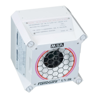
Introduces the FL500 UV/IR flame detector and its basic operating principles and features.
Explains the device's self-monitoring system for detecting optical path blockages.
Details the meaning of LED indicators for various device operational states.
Lists the necessary tools for installing the FL500 flame detector.
Provides guidance on selecting an appropriate installation site for the device.
Illustrates the detection range and angles for various fuel types, showing performance at different distances.
Details operating temperature, humidity, and factors that may cause false alarms.
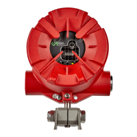
Provides instructions and considerations for physically installing the flame detector.
Explains the electrical connections and safety precautions for wiring the device.
Describes the function and layout of the device's terminal blocks for wiring connections.
Details the wiring and configuration options for the Alarm High relay output.
Explains the wiring and configuration for the Alarm Low relay output, including its immediate nature.
Describes the Fault relay wiring, its standard configuration, and conditions that activate it.
Details how to connect and use an external switch to reset latched alarm outputs.
Covers the device's analog output signals, Modbus RTU, and HART communication protocols.
Provides recommended cable lengths for interfaces and power supply based on cable AWG.
Specifies the voltage range and requirements for powering the FL500 detector.
Explains the importance and connection method for grounding the device chassis.
Discusses compatibility and configuration for wiring with standard fire alarm cards.
Provides safety guidelines for terminating cables in non-hazardous environments.
Outlines the steps and sequence for powering up and initializing the FL500 detector.
Explains how to modify device parameters using Modbus, HART, or DIP switch.
Provides step-by-step instructions for configuring device settings via the internal DIP switch.
Describes how to select HART current or use Modbus/HART for setting changes.
Explains how to verify the device's correct operation using a test lamp or feature.
Details the use of the TL105 test lamp for performing sensitivity checks on the detector.
Describes how to use the integrated alarm test function to simulate fire conditions.
Outlines routine tasks, including cleaning and sensitivity checks, for maintaining the device.
Provides instructions and warnings for cleaning the device's optical window and reflectors.
Details checks for wiring, terminal connections, and the stability of mounting hardware.
Provides guidelines for storing the device safely, including conditions and packaging for extended periods.
Lists common faults, their possible causes, and corrective actions for the FL500 detector.
Provides contact information and procedures for sending the device back to General Monitors for repair.
Advises on proper disposal procedures for the device according to environmental regulations.
Lists relevant standards, publications, and websites for additional product information.
Details application, device location, environmental ratings, and typical alarm response times.
Lists physical characteristics such as enclosure material, color, dimensions, and weight.
Covers supply voltage, current, output signals, relay ratings, and communication interfaces.
Provides operating/storage temperature, humidity range, and false alarm sources.
Lists the certifications and standards the FL500 detector meets, including CSA, FM, ATEX, IECEx, HART, and SIL.
| Measurement Range | 0-100% LEL |
|---|---|
| Resolution | 1% LEL |
| Detection Range | 0-100% LEL |
| Output | 4-20 mA |
| Approvals | ATEX, IECEx, CSA |
| Ingress Protection | IP66 |
| Gas Detected | Flammable gases |
| Protection Rating | IP66 |
| Certifications | ATEX, IECEx, CSA |