37
Specifications
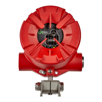
FL500 UV/IR Flame Detector
US
8.2 Mechanical Specifications
8.3 Electrical Specifications
Enclosure material 316 Stainless Steel
Color Red
Finish TGIC polyester powder coat
Height 6.4 in. (16.2 cm)
Width 5.0 in. (12.7 cm)
Depth 4.3 in. (11.0 cm)
Weight 9.4 lb (4.3 kg)
Cable Entry
2 x ¾ in. NPT (M25 adapters included for some config-
urations)
Earth Terminals
8-32 x 3/8 Philips pan-head screw, stainless steel,
zinc-plated, green dye; external stainless steel tooth
lock washer included. Applicable for connection of
4mm
2
or smaller.
Nominal supply voltage 24 Vdc
Supply voltage range 20 to 36 Vdc (measured at device)
Maximum supply current 200 mA during COPM only
Typical current 80 to 150 mA
Maximum output signal load 600 ohms
Output signal range 0 to 20 mA *
Fault signal 0 to 0.2 mA *
COPM fault signal 2.0 ±0.2 mA *
Ready signal 4.0 ±0.2 mA
IR only signal 8.0 ±0.2 mA
UV only signal 12.0 ±0.2 mA
Alarm Low signal 16.0 ±0.2 mA
Alarm High signal 20.0 ±0.2 mA
Relay contact ratings
North American Approved Applications:
SPDT, 5A @ 250 Vac, or 5A @ 30 Vdc resistive max.
European Union (EU) Approved Applications:
SPDT, 5A 30V RMS/42.4V Peak, or 5A @ 30 Vdc
resistive max.
RS-485 output
Modbus RTU
128 devices in series max.
(247 devices with repeaters)
Baud rate: 2400, 4800, 9600, or 19200 bps
HART
Fully HART 7 FieldComm compliant. Refer to the
FL500 HART Communication Operating Manual
(PN 10193215).
HART impedance RX = 50 K CX = 5 nF