27
Operation
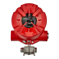
FL500 UV/IR Flame Detector
US
4 Operation
WARNING!
Make sure that there is no physical blockage from permanent objects such as structures and
equipment or temporary objects such as personnel and vehicles in the sensor's field of view. If
there is physical blockage in the sensor's field of view, the device cannot accurately monitor the
area for flame.
Make sure that there is no ice, dirt, or debris on the optical window. Blockage of the optical window
can result in a Fault condition.
During a Fault condition, the device does not monitor the area for flame.
Failure to obey these warnings can result in serious injury or death.
4.1 Start-Up
Before you supply power to the device, do the following:
• Replace the red dust cap with an applicable cable gland.
• Disconnect external devices such as automatic extinguishing fire suppression systems to prevent
activation.
• Make sure that the settings for the DIP switch are in the correct configuration. Refer to Section
4.2.1 "Using the DIP Switch" for instructions.
• Make sure that the device is mounted and wired correctly.
• Make sure that there is no blockage of the field of view for each device.
• Make sure that the optical window and reflectors are clean. Refer to Section 5.2 "Cleaning the
Optical Window" for cleaning instructions.
• Make sure that the power supply is connected correctly.
Apply power to the device. Each device starts a self-test start-up sequence. For the first 10 seconds,
the device sends 0 mA output, the Fault relay stays de-energized, and the green, yellow, and red
LEDs flash. After this 10-second period, the device sends 4 mA output, the Fault relay is energized,
the red LED goes off, and the green LED comes on and flashes every 5 seconds.
After the start-up sequence is complete, do a sensitivity check. Refer to Section 4.3 "Sensitivity
Check" for instructions.
4.2 Changing Device Settings
All device settings can be changed through Modbus, HART, or the DIP switch. Settings made through
Modbus and HART override settings made through the DIP switch.
4.2.1 Using the DIP Switch
To change device settings through the DIP switch, do the following:
(1) Use a flat-blade screwdriver to remove the screws that attach the detector head to the base
assembly.
(2) Find the DIP switch.
(3) Make the applicable switch assignments.
(4) Cycle power to the device.