25
Installation
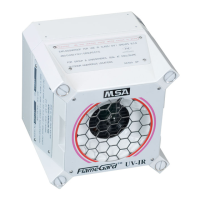
FL500 UV/IR Flame Detector
US
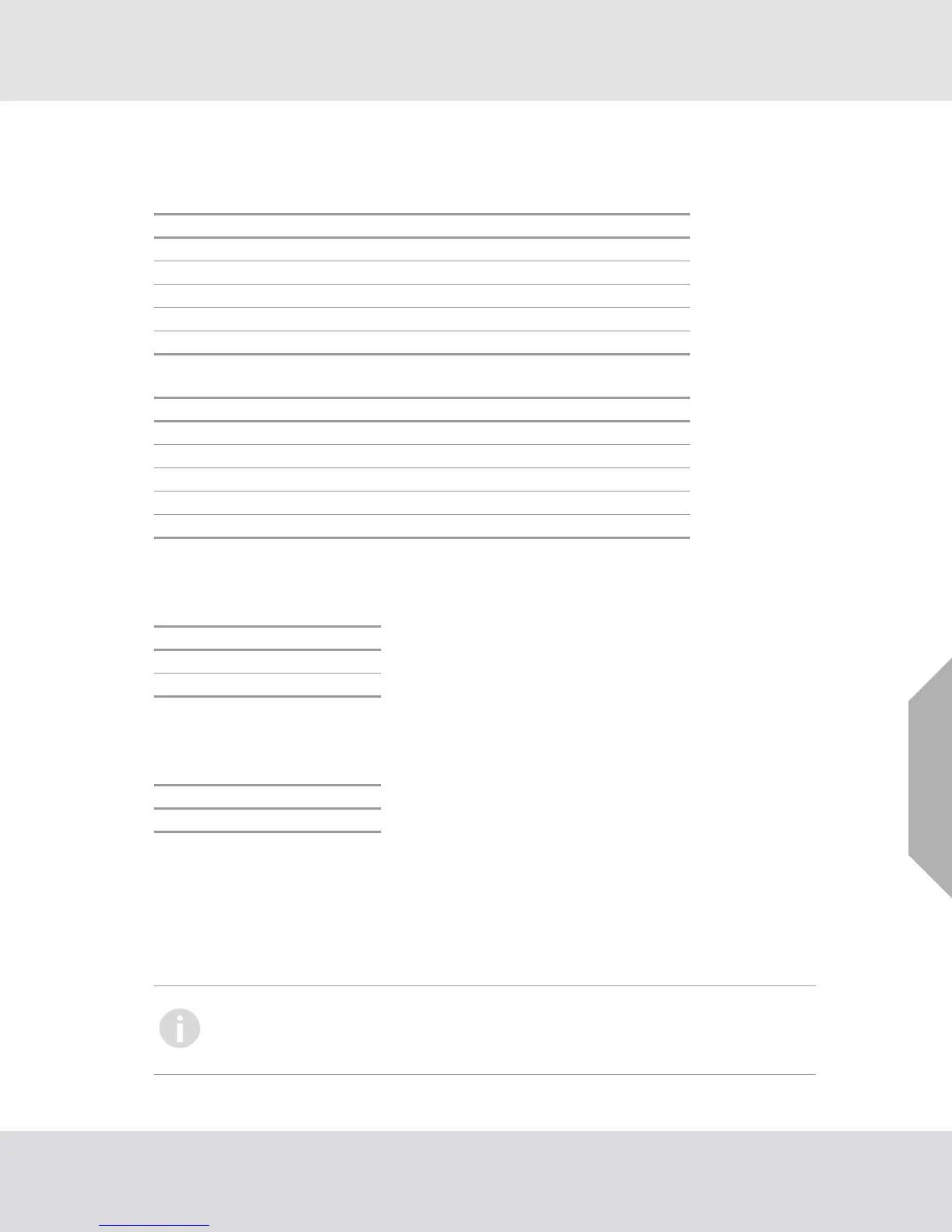
3.6 Cable Lengths
Use the following cable lengths (maximum 50-ohm loop) for interfaces with impedance devices that
have 250-ohm input.
Use the following cable lengths (maximum 20-ohm loop) for a 24 Vdc power supply.
3.7 Power Supply
The voltage range for the power supply is 20 - 36 Vdc at the device. Low voltage occurs at approxi-
mately 18.5 Vdc.
3.8 Chassis Ground
Use this connection to ground the device when you do any work with the wiring. General Monitors
recommends that the chassis be grounded at all times.
3.9 Fire Cards or Panels
General Monitors factory-fits end-of-life (EOL) and Alarm High resistors for devices that are wired
together to do monitoring through standard fire cards.
When the FL500 is used with a General Monitors Model IN042 card, the Alarm High resistor is set to
470 ohm and the EOL resistor is set to 5.6K. The EOL resistor is onboard the Model IN042 card and
can be selected through the DIP switch.
Cable AWG Run (ft) Cable (mm
2
) Run (m)
14 9000 2.50 2750
16 5800 1.50 1770
18 3800 1.00 1160
20 2400 0.75 730
22 1700 0.50 520
Cable AWG Run (ft) Cable (mm
2
) Run (m)
14 6588 2.08 2013
16 4146 1.31 1266
18 2608 0.823 796
20 1642 0.519 501
22 1055 0.33 321
TB1 Position Connection
324 Vdc
2COM
TB1 Position Connection
1 CHAS GND
European Union (EU) approved applications: Make sure that interconnecting cables
have an overall screen, or screen and armor. Cables BS5308 Part 2, Type 2, or equiv-
alent are approved for use. To make a positive electrical connection, make sure that the
cable armor connects to an applicable cable gland at the device.