36
Specifications
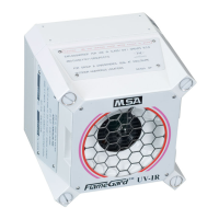
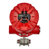
FL500 UV/IR Flame Detector
US
8 Specifications
8.1 System Specifications
* Applicable to FM approvals only.
Notes:
Response times and field of view data were derived by testing the device with a 1 ft
2
heptane fire. One
cup of heptane on top of a 1-in. layer of water was ignited for each test. These are typical values. The
variation of each fire can cause different results.
BS EN 54-10 identifies the limit of the field of view to ±25 degrees because of the requirements of the
Directional Dependence test. This result is from indoor benchtop testing with a Bunsen burner as the
fire source, rather than the outdoor flame testing used to identify the field of view in Section 3.2.1
"Field of View".
Application
UV/IR Flame
Detection
Device location
Class I, Division 1, Groups A*, B, C, and D
Class II, Division 1, Groups E, F, and G
Class III
Ex db IIC T5 Gb
Ex tb IIIC T100°C Db
II 2 G D
-50°C to 85°C under FM, -55°C to 85°C under
CSA/ATEX/IECEx
Environmental ratings Type 6P, IP66/IP67
UV Detector pass band 185 - 260 nanometers
IR Detector center wave-
length
4.35 mm
Typical alarm activation
response times
Fuel Distance (ft)
Response Time
(s)
n-Heptane
90
60
6
<3
Methane 80 <10
Methanol 40 12
Propane 60 <7
Ethane 60 <3
Butane 55 <3
Zeta value
Zeta = -0.001
The margin of error in the range measurement is esti-
mated at ±5 ft (±1.5 m) due to wind conditions and flame
turbulence.
Field of view Refer to Section 3.2.1 "Field of View" for information.