22
Installation
FL500 UV/IR Flame Detector
US
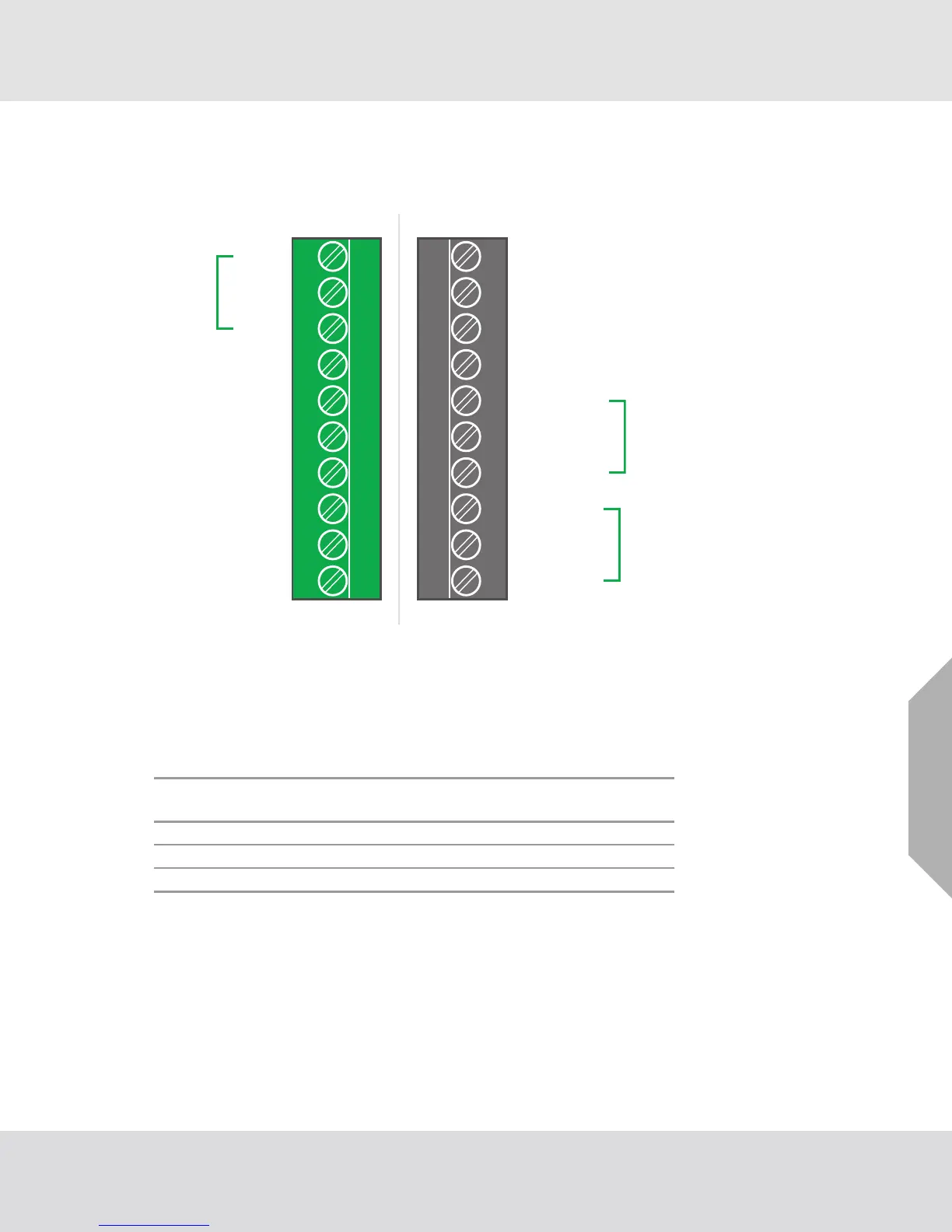
3.5 Terminal Connections
There are 20 terminal connections. The following sections give descriptions and specifications for
each connection.
Fig. 16 Field Terminations
3.5.1 TB2, Alarm High Relay Connection
The output for the SPDT Alarm High relay has a time delay that can be set for 2, 4, 8, or 10 seconds.
Alarm High output can be normally energized or normally de-energized, latching or non-latching.
All options can be set through Modbus, HART, or the DIP switch. Refer to Section 4.2 "Changing
Device Settings" for instructions.
TERM#TERM#
TB2TB1
11 12 13 14 15 16 17 18 19 20
12345678910
Chassis
COM (24 V - Return)
+ 24 VDC
0-20 mA
No Connection
Data +
Data −
Fault 1
Fault C
Fault 2
Alarm Low 2
Alarm Low 1
Alarm Low C
Alarm High C
Alarm High 1
Alarm High 2
Alarm Test
No Connection
No Connection
Alarm Reset
TB2
Position
Alarm High
Relay
Relay Contact
(De-Energized)
Relay Contact
(Energized)
7 C Common Common
6 1 Normally Closed Normally Open
5 2 Normally Open Normally Closed