21
Installation
FL500 UV/IR Flame Detector
US
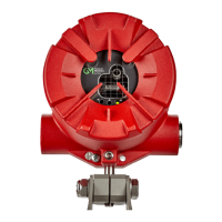
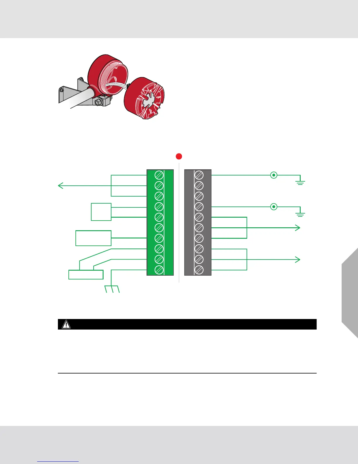
Fig. 14 FL500 Housing and Base
Remove the insulation from each wire to 0.25 in. (0.64 cm).
Use the correct cables for the ambient temperature where the device is installed.
Fig. 15 Wiring Diagram
Protection Circuits for Relay Contacts
WARNING!
Protect relay contacts from transient and over-voltage conditions. Attach a clamp to all inductive loads
(bells, buzzers, relays) on dry relay contacts as shown. Inductive loads that do not have a clamp
attached can cause voltage spikes of more than 1000 Volts. Voltage spikes of this magnitude can
cause false alarms and damage to the contacts.
Failure to obey this warning can result in serious injury or death.
(1) To connect the wire to the terminal block, install the conductor in the connection space as shown.
(2) Use a flat-blade screwdriver to tighten the related screw terminal.
Fault 2 Alarm Reset
No Connection
No Connection
Alarm Test
Alarm Low 2
Alarm Low 1 Alarm Low Relay
Alarm High Relay
Normally
Open Switch
Normally
Open Switch
Alarm Low C
Alarm High C
Alarm High 1
Alarm High 2
Fault C
Fault 1
No Connection
+ 24 VDC
0-20 mA
+−
COM (24 V-return)
Chassis Ground
Data −
Data +
RS485
TB2TB1
11 12 13 14 15 16 17 18 19 20
12345678910
Control Device
PLC, DCS, ETC
Power Supply