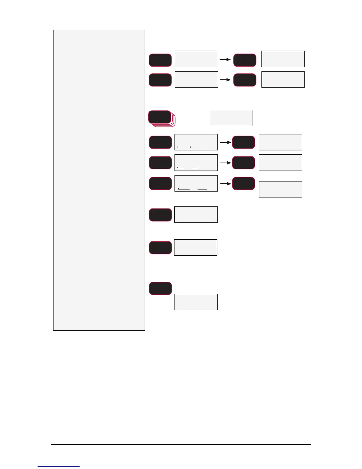
The first digit blinks. Use the
F2 key to scroll through the
numbers. When the desired
number is shown, push F1
.
In this example, we’ll enter 2500 as
a capacity.
Continue inputing the desired
capacity using the F2 key for
scrolling the number and the
F1 key to store the number.
fixed
blinking blinking
blinking
SCROLL
F2
SCROLL
F2
SCROLL
F2
ENTER/SELECT
F1
5 times
blinking
blinking
blinking
fixed
fixed
fixed
15) Finalize the capacity value
by pressing the F1
key on an
unblinking display. In our
example, once the number
2500 is fixed on the display,
press F1
to store the capacity
value.
16) Next the scale division size
d is set. Press F1 to begin.
In this example we’ll set the d to
2.
17)Use the F2 key to scroll
through the recommended
scale divisions. The first d
offered is the standard division for
the given capacity. Setting a ‘d’ size
that results in total resolution higher
than 1:5000 is not recommended
for stability reasons.
18)When the desired scale d
is displayed, press F1.
The UnLd display
appears and the scale is
ready for calibration.
Follow the standard
calibration procedure
starting at step 3.
G
blinking
XQ/G
Capacity is set.
d is set.
Proceed to Standard
Calibration starting at Step 3.
F2
SCROLL
ENTER/SELECT
F1
ENTER/SELECT
F1
ENTER/SELECT
F1
ENTER/SELECT
F1
SCROLL
F2
SCROLL
F2
ENTER/SELECT
F1
Next Cal Screen
blinking
SCROLL
F2
ENTER/SELECT
F1
14)