42 MSI-7300 Operator’s Manual
6.4 802.15.4 RF Network Setup
When equipped with the 802.15.4 option, the Dyna-Link 2 can connect with an
MSI-8000 Remote Display or
an 802.15.4 modem. The unit uses three numbers to
connect to an 802.15.4 piconet:
1. ScaleCore ID – uniquely identifies each ScaleCore device in a
piconet. It has a
range of 0-254 and must not be duplicated within the same RF channel. For the
MSI-8000 as network coordinator, MSI recommends a number for the Dyna-
Link 2 from 0-3 if multiple units will be connected to the MSI-8000. If a single
Dyna-Link 2 is all that’s needed than any number up to 254 is acceptable.
2. RF Channel – establishes the base network, all in
terconnected devices must
match. This number must be in the range of 12-23.
3. Network ID – this is a 64-bit number that all interconnected devices must match.
The Dyna-Link 2 li
mits this number to a max of 5 digits for a range of 0 - 99999.
Do not use a small number here to help avoid other 802.15.4 networks that
default to a network ID of 0.
4. RF Strength – Transmission strength can be set from 0 to 4, default is 1. The
settin
gs effect the transmission range with zero is lowest power level and four is
the highest. Power 4 will use the battery life quicker, so use the lowest number
possible for reliable transmission. If maximum range is needed set the strength
to four.
For all devices that interconnect, the RF channel and network ID must
match. The ScaleCore ID must be unique. The Dyna-Link 2 or other
MSI RF equipment that is a weight data source should be set to a
ScaleCore ID of 0, then if other slave devices are added, they can be
added in sequence.
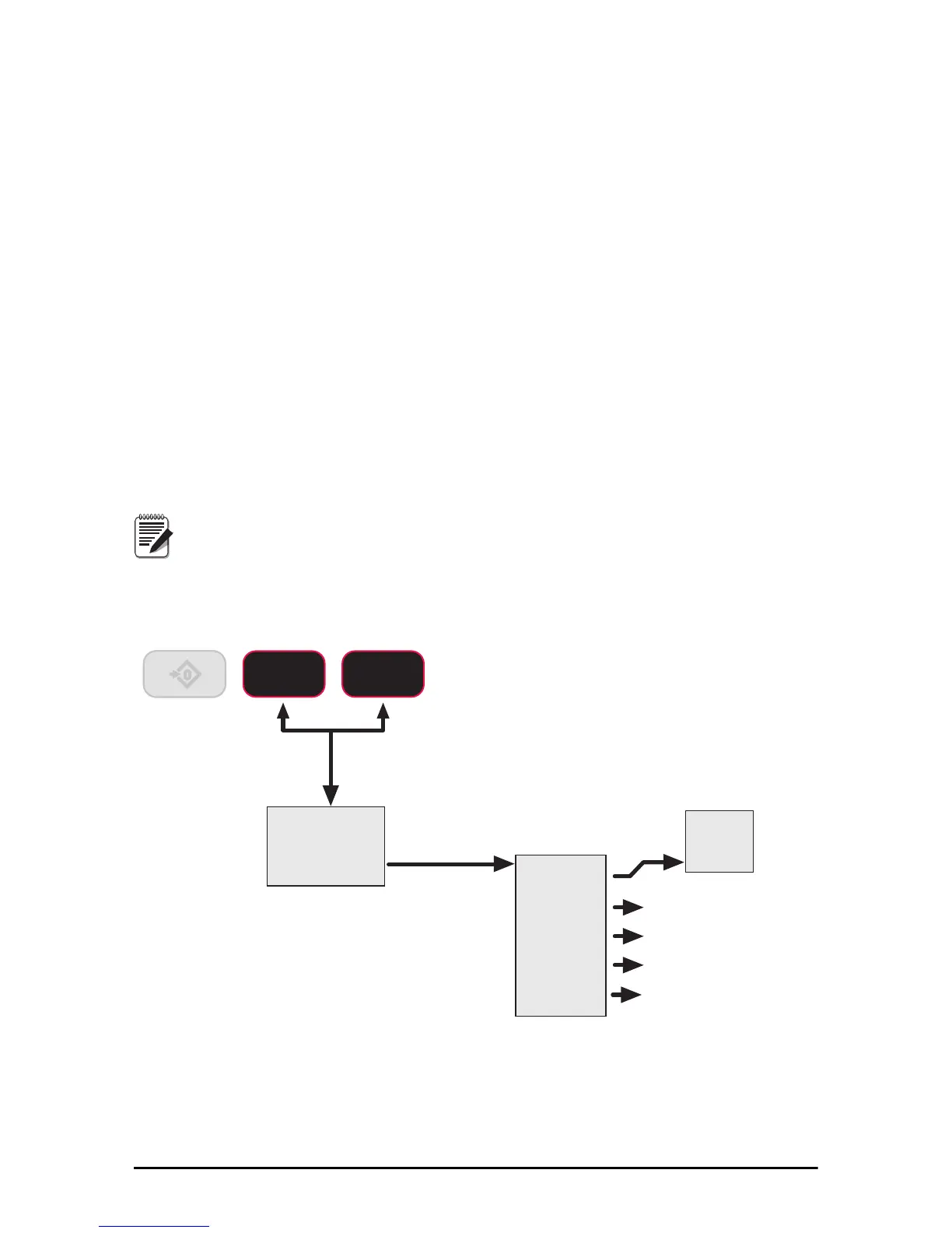
Figure 6-6 RF Menu