CRANKSHAFT, PISTON AND CONNECTING ROD
74
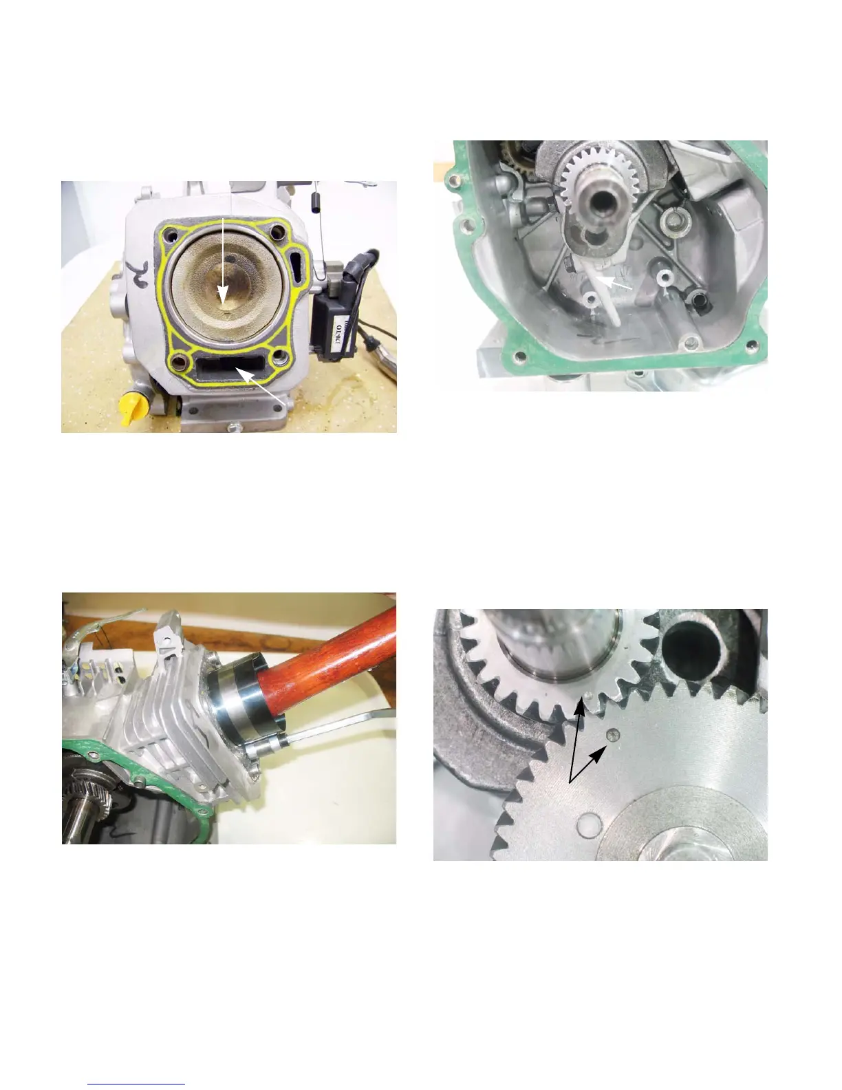
4c. Slide the connecting rod and piston into the
cylinder.
NOTE: The arrow on the piston must point
towards the push rod cavity.
See Figure 10.19.
4d. Tap the piston through the ring compressor
into the cylinder using a wooden hammer
handle.
See Figure 10.20.
NOTE: Make sure the crankpin is at BDC (bot-
tom dead center) to prevent damage from the
connecting rod.
4e. Pre-lube the connecting rod with clean 10W-
30 motor oil
4f. Install the connecting rod cap. Apply a small
amount of releasable thread locking com
-
pound such as Loctite® 242 (blue) to the
connecting rod bolts and tighten the cap
bolts to a torque of 106 -124 in-lbs (12 -
14Nm).
See Figure 10.21.
5. Install the valve tappets.
6. Install the cam shaft by:
6a. Pre-lube the cam shaft with clean 10W-30
motor oil
6b. Rotate the crank shaft until the timing mark
points to the tappets.
6c. Insert the cam shaft while aligning the timing
marks.
See Figure 10.22.
7. If removed, install the governor arm by following
the steps described in Chapter 4: Fuel systems
and Governor.
8. Place a new gasket on the crankcase cover, let
the alignment dowels hold it in place.
Figure 10.19
arrow
push rod
cavity
Figure 10.20
Tap piston with
hammer handle
Figure 10.21
Install the
connecting rod
cap
Figure 10.22
Timing marks
www.mymowerparts.com
For Discount White Outdoor Parts Call 606-678-9623 or 606-561-4983
 Loading...


