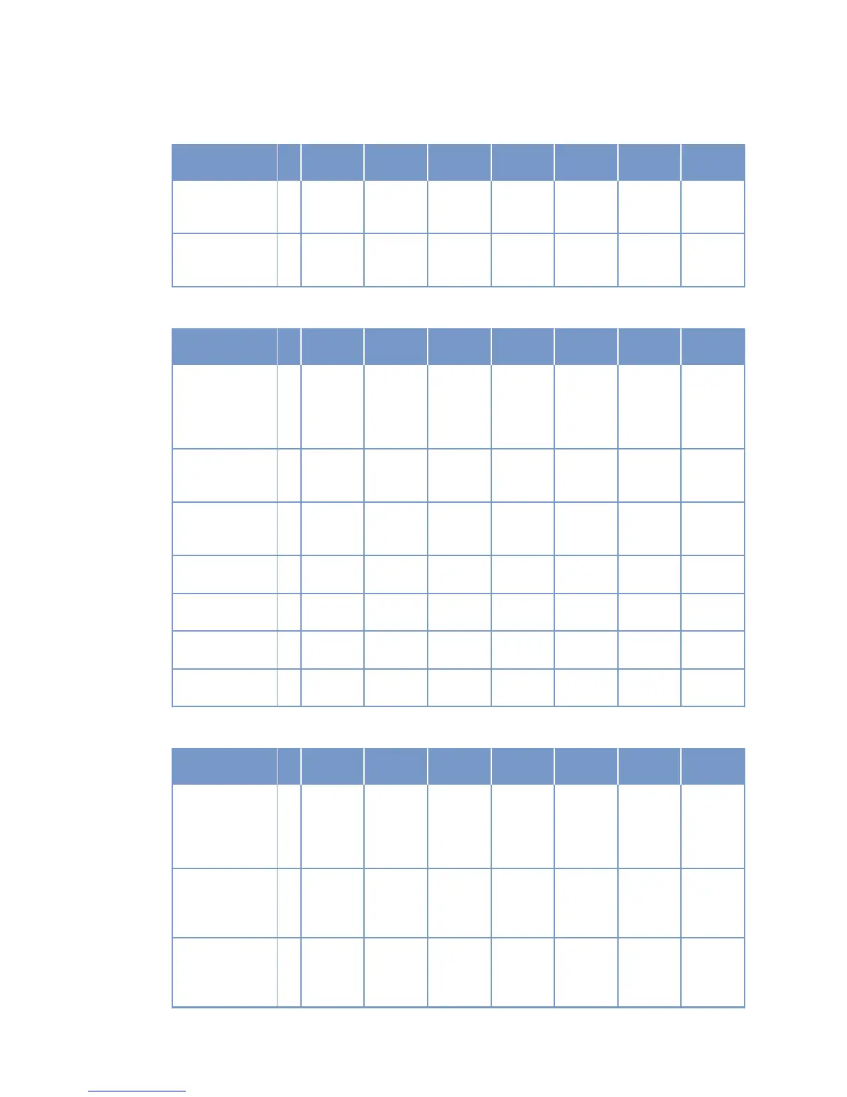
COMBUSTION AIR / EXHAUST GAS
Number of cylin-
ders
12V 12V 12V 16V 16V 16V
Charge-air pres-
sure before cylin-
der
R bar abs 2.4 2.6 2.8 2.6 2.9 3.0
3.1
Exhaust tempera-
ture after turbo-
charger
R °C 440 440 450 390 400 405
380
COOLANT SYSTEM (HT circuit)
Number of cylin-
ders
12V 12V 12V 16V 16V 16V
Coolant tempera-
ture (at engine
connection: outlet
to cooling equip-
ment)
A °C 100 100 100 100 100 100
Coolant tempera-
ture after engine,
warning
R °C 102 102 102 102 102 102
Coolant tempera-
ture after engine,
shutdown
L °C 104 104 104 104 104 104
Coolant antifreeze
content, max.
L % 50 50 50 50 50 50
Coolant pump: in-
let pressure, max.
L bar 2.5 2.5 2.5 2.5 2.5 2.5
Thermostat:
Starts to open
R °C 79 79 79 79 79 79
Thermostat: Fully
open
R °C 92 92 92 92 92 92
COOLANT SYSTEM (LT circuit)
Number of cylin-
ders
12V 12V 12V 16V 16V 16V
Coolant tempera-
ture (at engine
connection: outlet
to cooling equip-
ment)
R °C 53 54 55 55 57 57
56
Coolant tempera-
ture difference af-
ter/before inter-
cooler, min.
L °C 6 7 8 8 10 10
8
Coolant tempera-
ture difference af-
ter/before inter-
cooler, max.
L °C 14 15 16 16 18 18
16
34 | Technical Data | M015695/03E 2013-03
TIM-ID: 0000002924 - 002