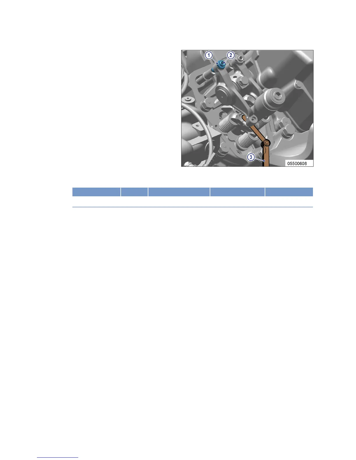
Adjusting valve clearance
1. Release locknut (1).
2. Insert feeler gauge (3) between valve
bridge and rocker arm.
3. Use Allen key to set adjusting screw (2) so
that the specified valve clearance is estab-
lished.
4. Feeler gauge (3) must just pass through
gap.
5. Tighten locknut (1) with torque wrench to the specified tightening torque, holding the adjusting
screw (2) to prevent it from turning.
Name Size Type Lubricant Value/Standard
Locknut M16 x 1.5 Tightening torque (Engine oil) 90 Nm +9 Nm
6. Replace or rectify adjusting screws and/or locknuts which do not move freely.
7. Check valve clearance.
Final steps
1. Remove barring device (→ Page 78).
2. Install cylinder head cover (→ Page 95).
94 | Task Description | M015695/03E 2013-03
TIM-ID: 0000000922 - 010