It is not possible to state a defined direction of rotation
(left or right), as different servo types respond dif-
ferently to control signals.
A brief press r on the 3-D digi-adjustor concludes the
process. The values are stored, and you can continue
with another servo.
The procedure for switching to another servo:
5. 4
Left to EXIT
6. r
Confirm REV appears
7. 4
Left to EXIT SERVO1 appears
Now continue with step 3 (selecting the servo) in the
preceding table.
The correct control surface response at the model:
Movement at the
Stick
Stick Control surface,
viewed from the
tail
RUDDER left left
ELEVATOR back (pull) up
AILERON left left aileron up
Note for V-tail models:
It is not necessary to check the direction of rotation
If your model features a V-tail, do not check the direc-
tion of rotation of servos 2 and 3 (elevator / rudder) at
this point. The directions of rotation can only be
checked and corrected when the V-tail mixer has been
activated (Î 13.7.1.).
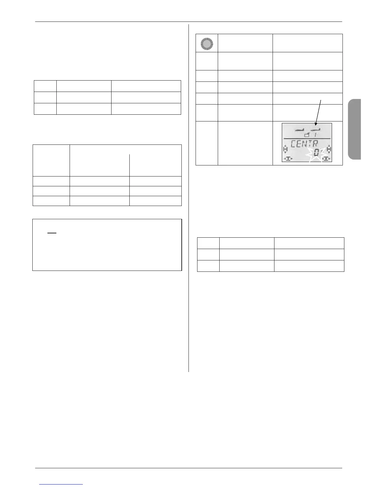
13.4.2. Adjusting the servo centre
Menu: (
SERVO) CENTR
Minor deviations in the control surface neutral position
can be corrected by adjusting the servo centre. Any
major deviation must first be corrected mechanically.
This is the procedure:
Action Effect
1. 4
r
Left to MENU
Confirm SETUP appears
2. 3
Right to SERVO
3. r
Confirm SERVO1 appears
4. 43
Select servo Servo number appears
5. r
Open selected servo
for setting
CENTR appears
6. r
Open CENTR
for setting
The current setting for CENTRE flashes in the bottom
line. If you are setting up a new model, the centre is set
to “0%” by default.
The centre can be set to any value within the range -
110% to +110% using the 3-D digi-adjustor.
A brief press r on the 3-D digi-adjustor concludes the
process. The value is stored, and you can continue
with another servo.
Switching to another servo:
7. 4
Left to EXIT
8. r
Confirm CENTR appears
9. 4
Left to EXIT SERVO1 appears
Now continue with step 4 (selecting the servo) in the
preceding table.
13.4.3. Setting servo (control surface) travels:
Menu: (
SERVO) TRAVL
The building instructions for your model should include
a table of recommended control surface travels.
In the TRAVEL menu you can set the travels to the
desired value “electronically”, separately for each side
of centre.
Servo travel can be set to any value within the range -
110% to +110%.