You can only check the assignments using the 3-D
digi-adjustor 4 3. The meaning of the displays is
as follows:
0 = function cannot be transferred to the Pupil
1 to 5 = channel used by Pupil transmitter
x R = Pupil signal reversed
1. Move one control at the Teacher transmitter
to one of the two end-points (Quick-Select)
and then return it to centre (e.g. up-elevator).
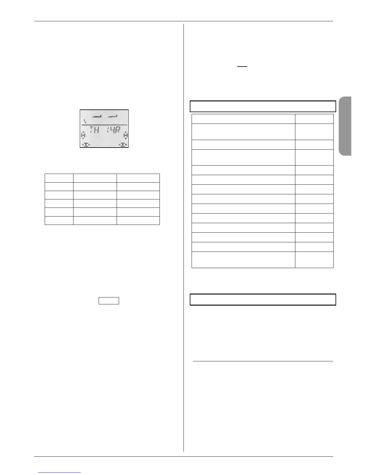
The screen must show the code for the transmitter
control you have moved. The channel number 0 or
1 to 5 must flash.
Example: throttle comes from channel 4 on the Pupil trans-
mitter, and is reversed.
Functions which can be controlled by the Pupil:
Code Fixed-wing Heli
AI
Aileron Roll
EL
Elevator Pitch-axis
RU
Rudder Yaw
TH
Throttle Collective pitch
SP
Spoiler Throttle Limiter
2. At the Pupil transmitter move the transmitter con-
trol to the same end-point, then return it to centre
(including throttle and spoiler).
3. Repeat steps 1 and 2 until all the desired functions
have been assigned.
The assigning process can be concluded in two ways:
a. with a brief press r on the 3-D digi-adjustor;
the ASSIGN menu re-appears.
b. with a long press ª on the 3-D digi-adjustor;
this takes you to the INFO 1 display. The name of
the selected model alternates with TEACHER.
! Now check the direction of effect of all the
model’s functions which are to be controlled
by the Pupil.
Changing the direction of effect or the assignment
for the Pupil:
a. If you are no longer at the Assign menu:
Move to the ASSIGN menu (see above)
Open the menu with a brief press r on the 3-D
digi-adjustor
b. Repeat steps 1 and 2 (see above).
Erasing the assigned functions:
a. If you are no longer at the Assign menu:
Move to the ASSIGN menu (see above)
Open the menu with a brief press r on the 3-D
digi-adjustor
b. Use the 3-D digi-adjustor (34) to select the con-
trol function; erase the assignment with a long
press ª on the 3-D digi-adjustor (“0” appears next
to the function).
20.3.5. Notes on Trainer mode operations
! The TEACHER button must be held pressed in
all the time the Pupil has control!
! Check all the working systems before take-off!
Check the direction and travel of all functions on
the Teacher and
Pupil transmitters.
! Take care that nothing disturbs the concen-
tration and attention of the Pupil while he or
she is flying the model!
(spectators, other model pilots, ...)
21. Accessories and spare parts
Item Order No.
Channel-Check PLUS, 35 MHz
Channel-Check PLUS, 40 / 41 MHz
# 4 5174
# 4 5175
Transmitter aerial, 140 cm (standard)
# 89 3001
Stub aerial, 35 MHz
Stub aerial, 40 / 41 MHz
# 7 5126
# 7 5127
Aerial ball-joint
# 7 5129
Aluminium stick-tops
# 7 5304
Tx. battery, 6 cells, NiMH, 1500 mAh
# 15 6001
Transmitter case
# 76 3323
Transmitter tray
# 8 5306
PROFI transmitter neckstrap
# 8 5646
Padding for PROFI neckstrap
# 8 5641
“Cross-over” transmitter support strap
# 8 5640
Simulator interface lead, USB
# 8 5153
Trainer lead (straight plug)
Trainer lead (right-angled plug) (Î 20.)
# 8 5121
# 8 5118
For more information regarding accessories and re-
placement parts please refer to the current main cata-
logue or our Internet website: www.multiplex-rc.de.
22. Multi-function socket interfaces
The multi-function socket of the COCKPIT SX has the
following functions:
• Charging / discharging the transmitter battery Î 8.
• Diagnosis mode Î 22.1.
• PC socket for flight simulator Î 22.2.
22.1. Diagnosis mode
A receiver can be controlled from the transmitter via
cable, using what is known as diagnosis mode (direct
servo control), without radiating an RF signal, e.g. if the
channel is already in use by another modeller. Connect
the transmitter (via the MULTIPLEX multi-function
socket) to the receiver (via the charge socket on the
switch harness # 8 5039 or # 8 5046) using the Diag-
nosis lead. Diagnosis mode is only possible with MUL-
TIPLEX receivers which feature a combined battery /
diagnosis socket “B/D”.
The connecting lead required is available from model
shops under the Order No. # 8 5105.