Moving to the START1 menu:
4 to MENU, r (SETUP appears),
3 to TIMER, r (START1 appears),
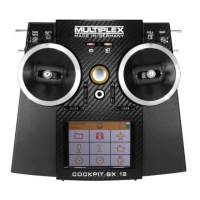
r
Start time for Timer 1 in minutes : seconds
The first number of the current start time flashes. Use
the 3-D digi-adjustor to set the “tens” of minutes. A brief
press r on the 3-D digi-adjustor takes you on to the
next digit.
Once you have set the “single second digits”, a brief
press r on the 3-D digi-adjustor concludes the process.
Important: the current time is stored.
The current time of Timer 1 is stored when you switch
the transmitter off. If you want the set time to start
again next time you switch on, you must first reset
Timer 1 in the INFO 2 or INFO 3 menu (long press
ª on the 3-D digi-adjustor).
If the assigned switch is at the ON position when you
switch the transmitter on again, Timer 1 immediately
resumes counting.
19.2. Timer 2
Timer 2 is ideal for recording the overall flight time. It
always starts at 00:00. The transmitter control selected
as the timer switch can start Timer 2, but it cannot stop
it again.
Timer 2 runs to a maximum of 99 minutes, 59 seconds.
Timer 2 can be started, for example, when the throttle
is advanced for the first time, when the tow-release is
operated, or when you operate the PH switch to switch
from the launch setting to normal flight.
19.2.1. Assigning a timer switch
Menu: (
TIMER) T2 SW
Example 1: starting Timer 2 using the THROTTLE
In this case the switch is assigned using the method
described in section Î 19.1.1.
Example 2: starting Timer 2 using the PH switch
Requirements:
The model must be programmed with flight phases.
Flight phase 1 is the “launch setting”, and flight phase 2
is “normal flight”.
The following example shows how to start Timer 2 (with
the stated requirements fulfilled), when you switch for
the first time from the “launch setting” to “normal flight”.
Moving to the T2 SW menu:
4 to MENU, r (SETUP appears),
3 to TIMER, r (START1 appears),
3 to T2 SW r
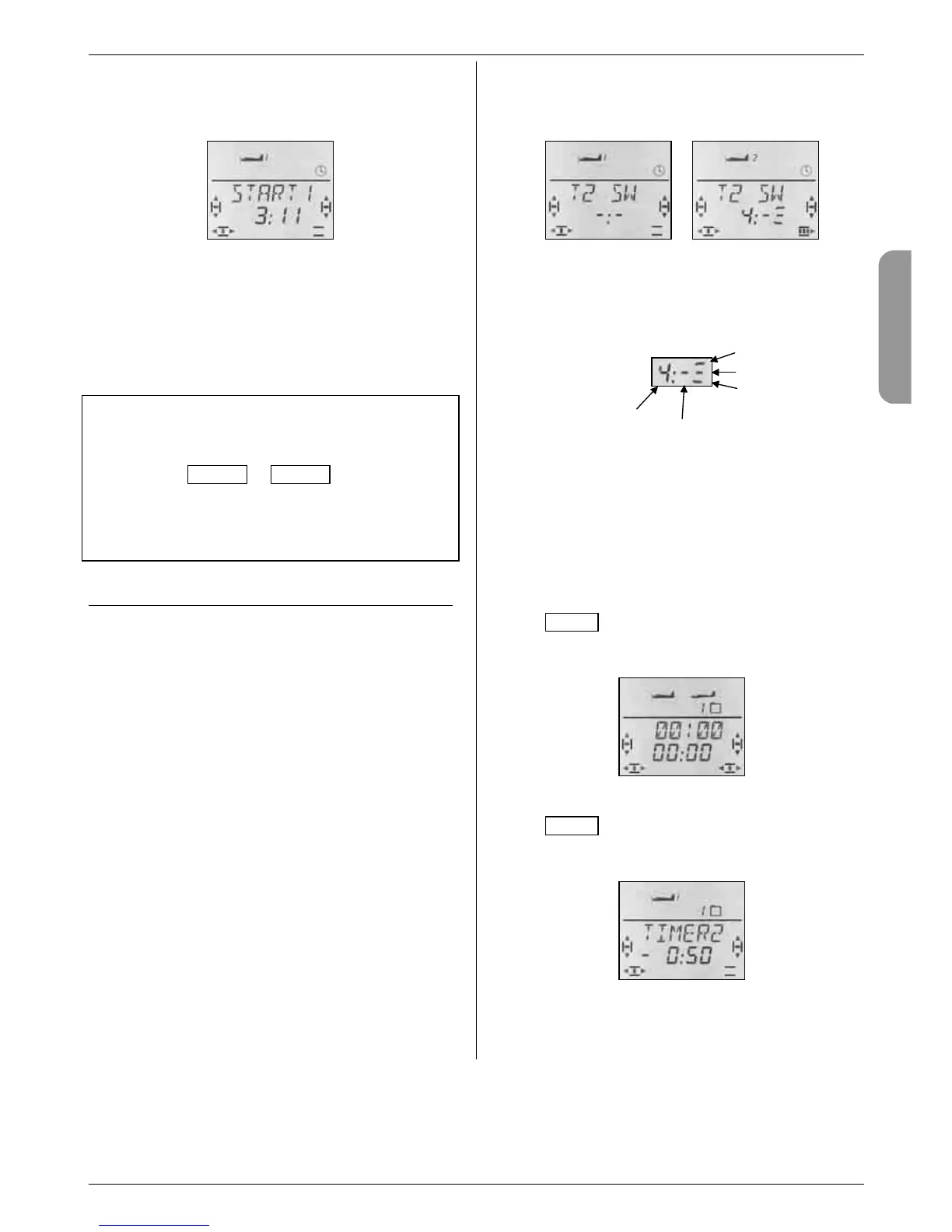
No switch Switch 4
Move the PH switch quickly to and fro until code num-
ber 4 appears. The hyphen following the colon indi-
cates the switch position which triggers the timer.
Switch 4 Marker Switch position
Now move the PH switch to the position which is re-
quired to trigger the timer (in our illustration Phase 2).
A brief press r on the 3-D digi-adjustor concludes the
process. The flashing ceases, and the setting is stored.
19.2.2. Stopping Timer 2, or resetting it to 00:00
Timer 2 can only be stopped or reset if it is visible in
the bottom line of the screen. There are two methods of
doing this:
In the INFO 3 display:
Pressing the 3-D digi-adjustor at this display affects
both timers.
INFO 3 display: both timers
In the INFO 4 display:
Pressing the 3-D digi-adjustor at this display only af-
fects Timer 2.
INFO 4 display: Timer 2 only
Stop timer: r brief press on 3-D digi-adjustor
Setting timer to 00:00: ª long press on 3D digi-adjustor
Phase 3
Phase 2
Phase 1