COCKPIT SX
Page 66
16.6.3. Throttle for electric helicopters
For electric helicopters you can generally leave the
servo travels at -100% / 100%. This setting corre-
sponds to the UNI signal format, and works with most
speed controllers.
However, it is important to check the working of the
THR-CUT button (emergency motor OFF): if the motor
runs to full-throttle when you press this button, you
must reverse the throttle channel (servo 5) in the
SERVO REV menu.
(Brief instructions, servo reversing Î 16.4.1.)
16.6.4. Setting up the throttle curve
Menu: (
CONTRL) TH
If you have just set up a new model memory, the five
points of the throttle curve are set as follows by default:
P1 = 0%, P2 = 25%, P3 = 50%, P4 = 75%, P5 = 100%
The purpose of the throttle curve is to maintain rotor
speed as nearly constant as possible over the full
range of collective pitch. The individual points on the
throttle curve have to be adjusted to match the energy
requirement for each collective pitch setting.
There are two methods of setting the throttle curve:
a. Selecting the points using the collective pitch
stick
(Quick-Select)
4 to MENU, r, (SETUP appears)
3 to CONTRL, r, (DR AI appears)
3 to TH, r
If you now move the collective pitch stick, the last
number indicates which point on the throttle curve
is currently selected.
A brief press r on the 3-D digi-adjustor opens the
parameter; select one of the five points using the
stick, and set the appropriate value.
A further brief press r stops the value flashing; you
can now check the values of the five points, but
you cannot change them.
The advantage of this procedure:
You can quickly and easily check the curve points
and - if necessary - change them, without have to
leave the menu.
b. Selecting the points using the
3-D digi-adjustor
(5 menus with the points P1 to P5)
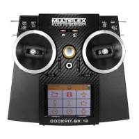
4 to MENU, r, 3 to CONTRL, r,
3 to TH, r (TH QS1 appears)
Select the desired point (4 3) using the 3-D digi-
adjustor
(TH P1 to TH P5)
If you turn the 3-D digi-adjustor further to the right,
you will move to the parameter TH MIN after
TH P5.
A brief press r on the 3-D digi-adjustor opens the
parameter, and you can set the desired value.
A further brief press r stops the value flashing.
You can now move on to another point on the
throttle curve using the 3-D digi-adjustor, or leave
this menu via EXIT.
The advantage of this procedure:
We assume that your model’s motor is already
running, and you wish to raise the throttle for col-
lective pitch maximum:
In this case you can select point 5 on the throttle
curve without having to move the collective pitch
stick to the maximum position.
Notes:
Three throttle curves with active flight phases
If you have activated flight phases (PHASES = 1), you
can set a different throttle curve for each phase.
No throttle curve for AUTO-ROTATION
When you operate the CS / A-ROT switch to select
auto-rotation, the fixed throttle value for auto-rotation is
generated. (Î 16.6.6.)
16.6.5. Setting throttle minimum (idle)
Menu: (
CONTRL) TH MIN
TH MIN (Throttle Minimum) limits the idle setting for the
motor at the bottom of its range, preventing the danger
that the motor might cut when throttled back. This value
can be raised by up to 30% using the trim (trim button
adjacent to the collective pitch stick). The only way to
reduce the throttle below the THRMIN level is press the
THR-CUT button.
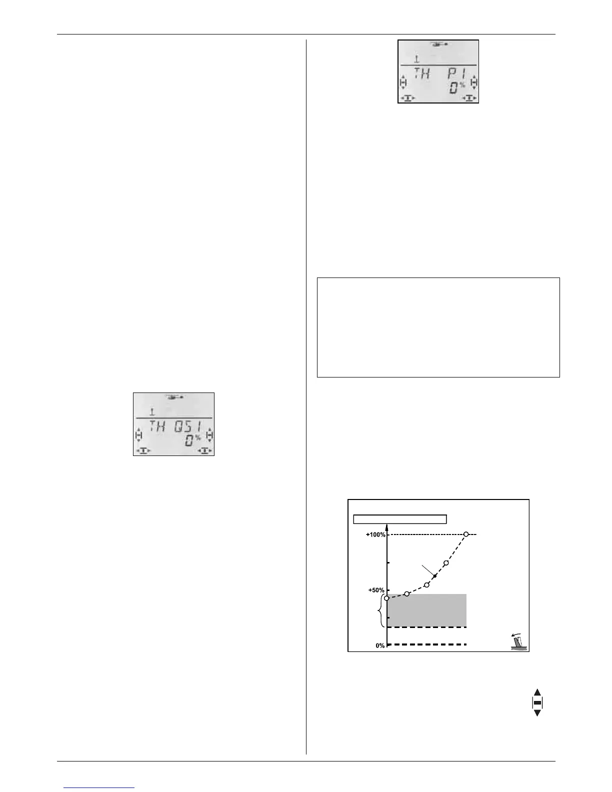
THR-CUT
Throttle for helicopters
Throttle on receiver output 5
Throttle curve
Trim
zone
(30%)
Throttle min.
TH MIN
Fig. 16.6.2.
TH MIN for glow motors
Set the throttle trim (trim rocker adjacent to the
collective pitch stick) to centre. The screen now
displays the symbol shown on the right.