Tool LCD Display
10
When the Tool is turned on in the folded position it starts with the message “Position Arms” that indicates that the arms
need to be deployed to one of the arm positions. Once the arms are deployed the message “Starting Solution” appears
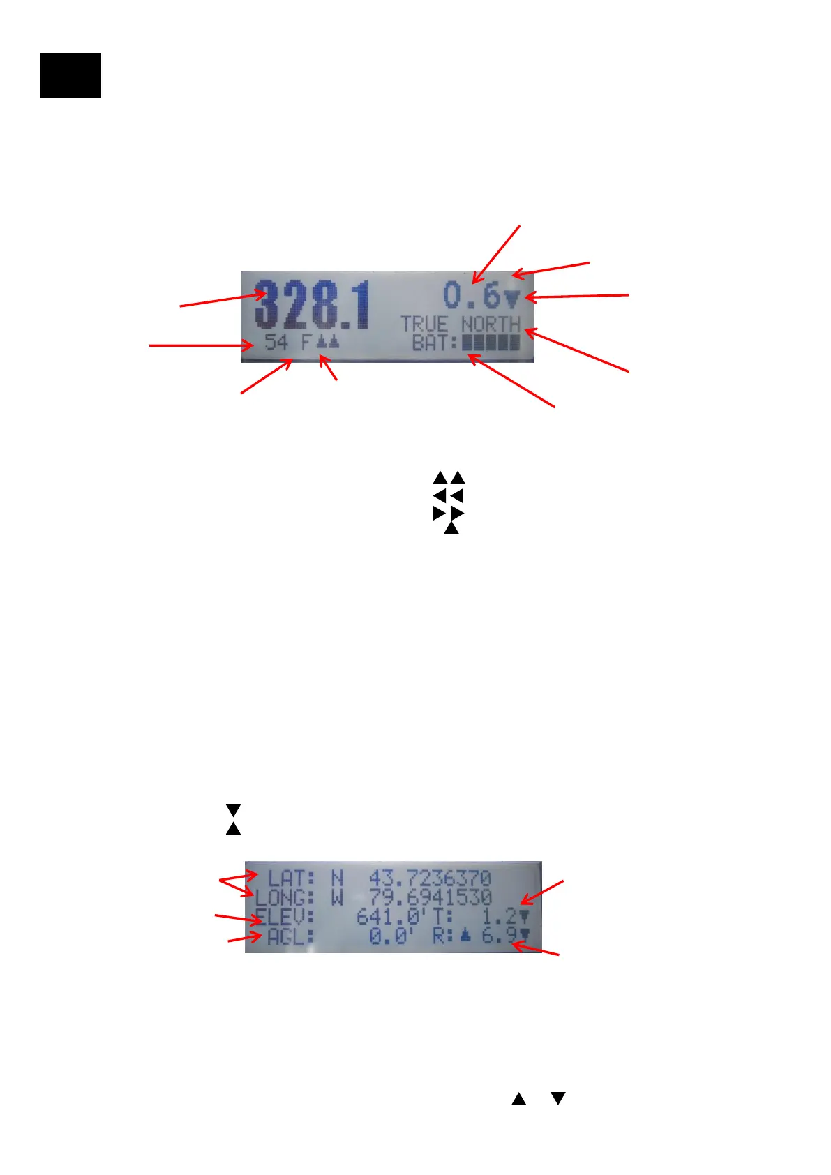
and an azimuth solution is being calculated. Once calculated the Azimuth, Azimuth Type, Tilt, Tilt Direction, GPS Integrity,
Battery and Bracket/Arms position is displayed on the main screen. The secondary screen (displayed by pressing the
down arrow on the User Interface) displays the GPS coordinates, Elevation, Tilt, Tilt Direction, Roll, Roll Direction, and
AGL.
LCD Display
Azimuth (deg)
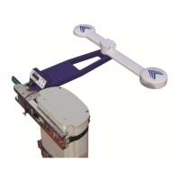
1. Tool on Bracket Position: Front (shown), Right, Left, Back
2. Arm Positions
Forward: Small Arm Forward:Long Arm Forward (shown)
Left T: Small Arm Left:Long Arm Left
Right T:Small Arm Right: Long Arm Right
Folded: Small Arm Folded: Long Arm Forward --
1
2
Tilt (deg)
BAT: Battery indicator
3. GPS Integrity: Value from 0 to 100 to determine the quality of
the azimuth measurement. It is a proprietary algorithm based on
GPS Satellite and calculated diagnostics.
GPS Integrity > 70: Excellent
GPS Integrity > 60: Very Good
GPS Integrity > 30: Good
3
4. Azimuth Type:
TRUE NORTH is used throughout most of the world for
aligning antennas. NO MAGNETIC DECLINATION IS
REQUIRED
GRID NORTH: Some areas in the UK and other
European countries
4
5
5. Tilt Direction: Downtilt
Uptilt
Main Screen
Secondary Screen
7
10
8
6
9
6. LAT, LONG: Latitude and Longitude
7. ELEV: Elevation from the GPS
8. AGL: From Laser Rangefinder
9. Tilt: “T” for Tilt. The arrow shows the Tilt Direction
10. Roll: “R” for Roll. The two arrows show the Roll Direction. The example 6.9 shows the
tool Rolled to the right side
11