Cube67 System Manual
21 V 2.5
Table 3-12 : Overview of MICO variants
Rated operating branch-circuit current
(full load)
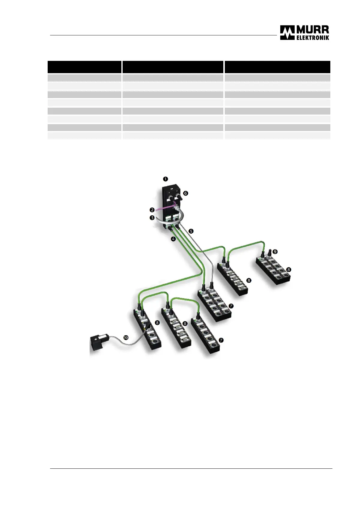
3.2.3 Topology
Fig. 3-2 : Topology
Bus node Field bus terminal resistance
Field bus line Compact module
Auxiliary power supply Expander module
Internal system connection Terminal resistance of internal system connection
External actuator supply Sensor/actuator
The bus node has four connections for I/O modules. It is not necessary to set the addresses of the
modules. The modules are actuated automatically in the order of connection. Unused connections are
ignored, i.e. it is possible to connect a module to socket 0, leave socket 1 unused, and connect the next
module to socket 2.

 Loading...