Cube67 System Manual
26 V 2.5
3.4 Connecting Sensors and Actuators
3.4.1 Sensor Power Supply
Sensors can be supplied by the I/O module
3
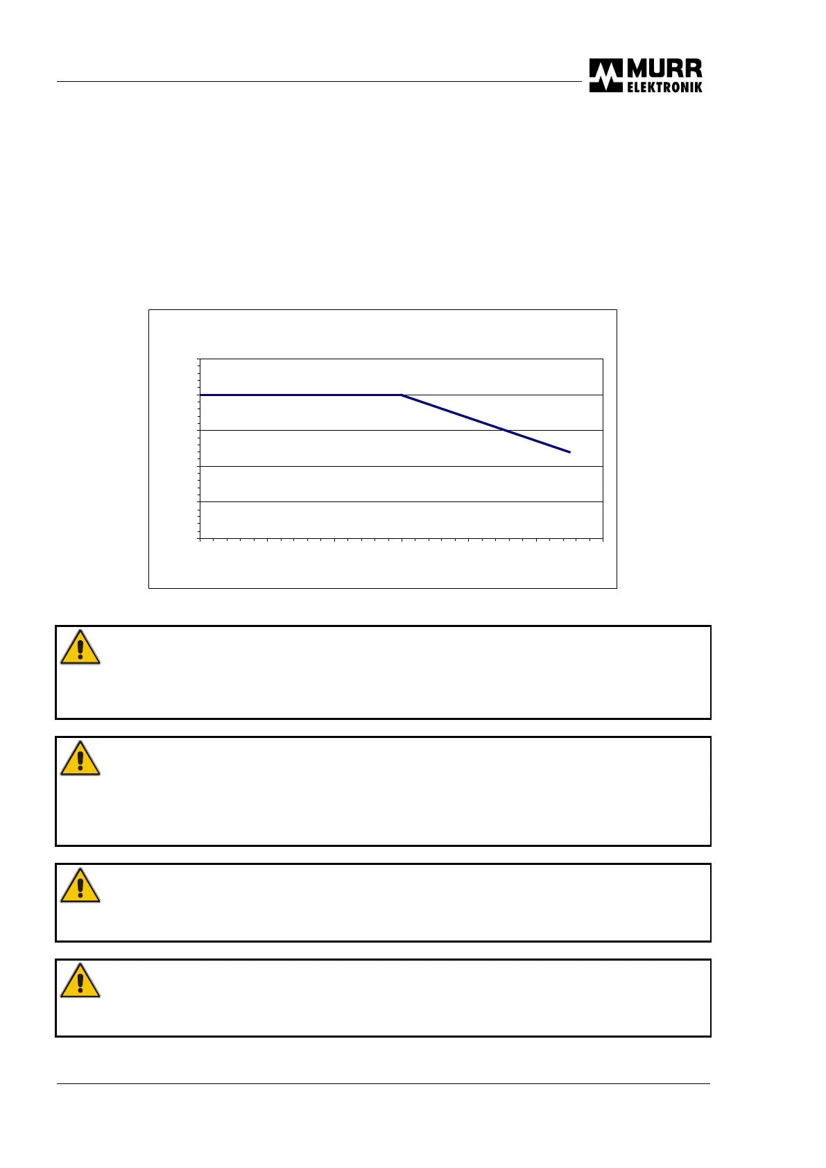
. One resettable PTC per M12 socket protects the sensor
supply. The maximum current draw for the sensor power supply is 200 mA for each M12 socket. Please
note the following derating diagram.
Derating Sensorversorgung
0
50
100
150
200
250
0 10 20 30 40 50 60
Fig. 3-5 : Derating sensor supply
CAUTION:
Please note that the sum current of all sensors and modules supplied via the bus
node in a Cube67 system may not exceed 9 A.
CAUTION:
Sensors can only be supplied via the bus node in a Cube67 system. Feedback
by sensors or an external power supply (in order to increase the max. current) is not
permissible.
ATTENTION:
Capacity per digital input is 10 nF.
ATTENTION:
The maximum permitted capacitance may not exceed 220 µF.

 Loading...