Cube67 System Manual
33 V 2.5
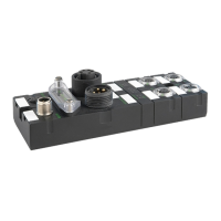
4 Index of Figures
Fig. 3-1 : The Cube67 System .................................................................................................................... 10
Fig. 4-1 : Topology ...................................................................................................................................... 21
Fig 4-2 : Use of the Cube67 PD 7/8” power distributor (example) ............................................................. 22
Fig. 4-3 : Terminating the internal system connection (example) ............................................................... 23
Fig. 4-4 : Derating sensor supply ................................................................................................................ 26
Fig. 4-5 : Connecting sensors/actuators with diagnostic outputs ................................................................ 28
Fig. 4-6 : Monitoring a line for line breaks ................................................................................................... 29

 Loading...