Cube67 System Manual
28 V 2.5
To increase power, outputs may be connected in parallel.
If an overload or short-circuit occurs at an output, the output affected is disabled. This
output remains disabled even after the fault is rectified. In order to reset the short-
circuit memory, reset the output or switch off the actuator power supply.
3.4.5 DESINA Diagnostic Input
Pin 2 of the M12 socket can be configured as a diagnostic input on all modules. If a 0 volt signal is
present at a diagnostic input , it is displayed inverted in the process map. At the same time, a channel-
specific diagnostic message is issued in the diagnostic data.
3.4.5.1 Examples of Application of DESINA Diagnostic Function Pin 2
Pin 2 basically behaves like an inverting input when it is configured as a diagnostic input.
The special thing about Pin 2 is that the assigned LED lights up red when a voltage of 0 V -> logical "1" is
applied. It is therefore possible to indicate faults on external devices at Cube67. Several proposals are
given in the following.
3.4.5.2 Connecting Sensors/Actuators with Diagnostic Output
Imagine you are using a sensor or an actuator with a diagnostic output. You can evaluate this diagnostic
signal. You can also process and display it on the controller or visualization unit using a conventional I/O
system. Two inputs are always required.
However, you have no visual fault display in the proximity of the defective sensor, which is probably also
fitted in a concealed location. Visual indication at the M12 socket of the Cube67 also helps accurate
onsite fault localization.
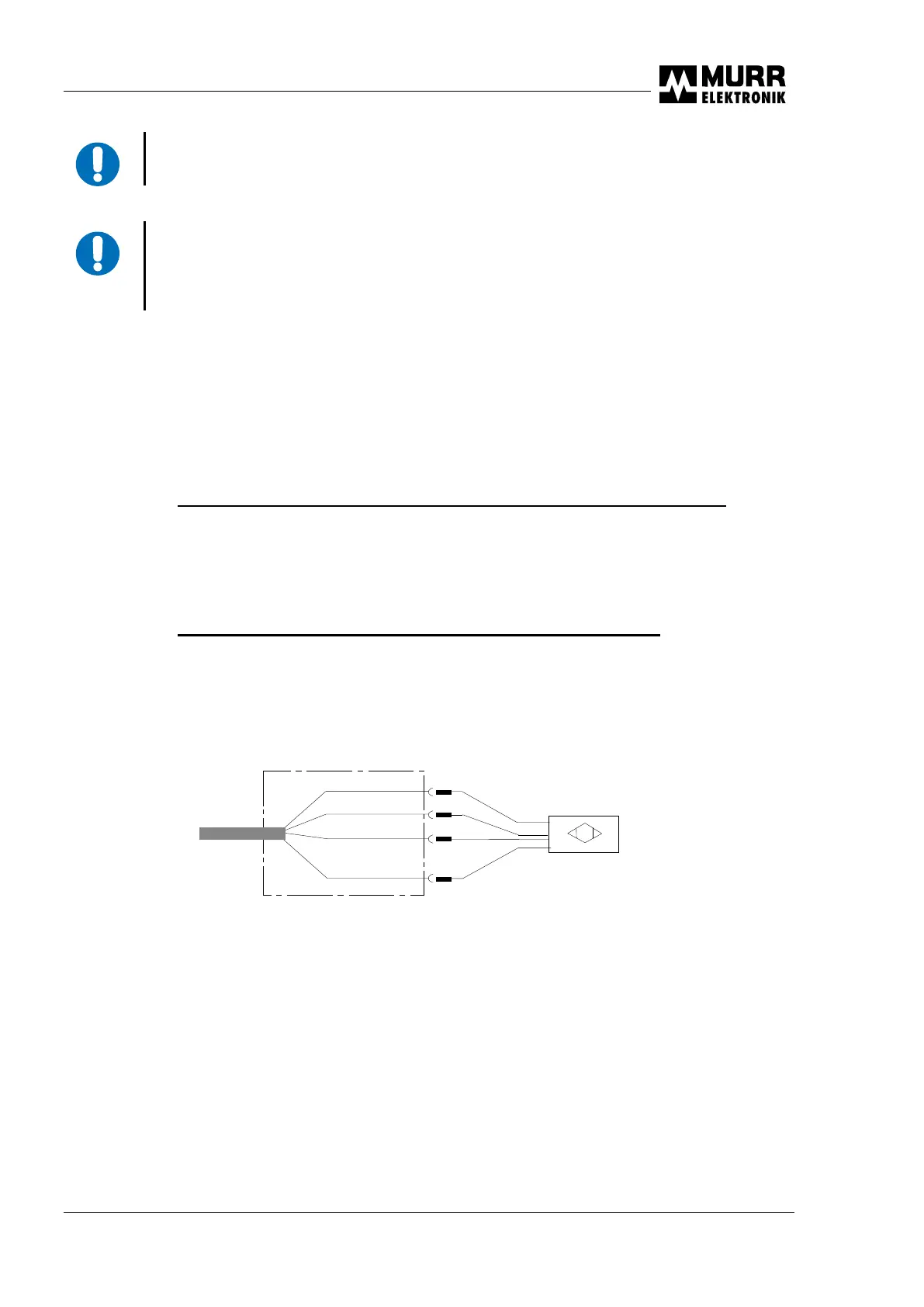
Fig. 3-6 : Connecting sensors/actuators with diagnostic outputs
Detection of :
- Damage to the end face
- Defective electronics
- Wire break

 Loading...