Chapter 3 Configuring Your SCXI Hardware and Software
Getting Started with SCXI 3-12 www.ni.com
Your SCXI-1120 is shipped in the 4 Hz position. Verify that both
stages are set to the same bandwidth to ensure that the required
bandwidth is achieved. Notice that one jumper block is available for
each filter stage.
♦ SCXI-1120D Filter Jumpers
Two-stage filtering is also available on your SCXI-1120D module. The
first stage is located in the isolated section of the input channel,
whereas the second stage is located in the nonisolated section of your
input channel. Two-stage filtering eliminates the noise generated by
the isolation amplifier, producing a higher signal-to-noise ratio.
Furthermore, two filter bandwidths are available, 22.5 kHz and
4.5 kHz.
4 W21-A W21-B W33 W34
5 W22-A W22-B W35 W36
6 W23-A W23-B W37 W38
7 W24-A W24-B W39 W40
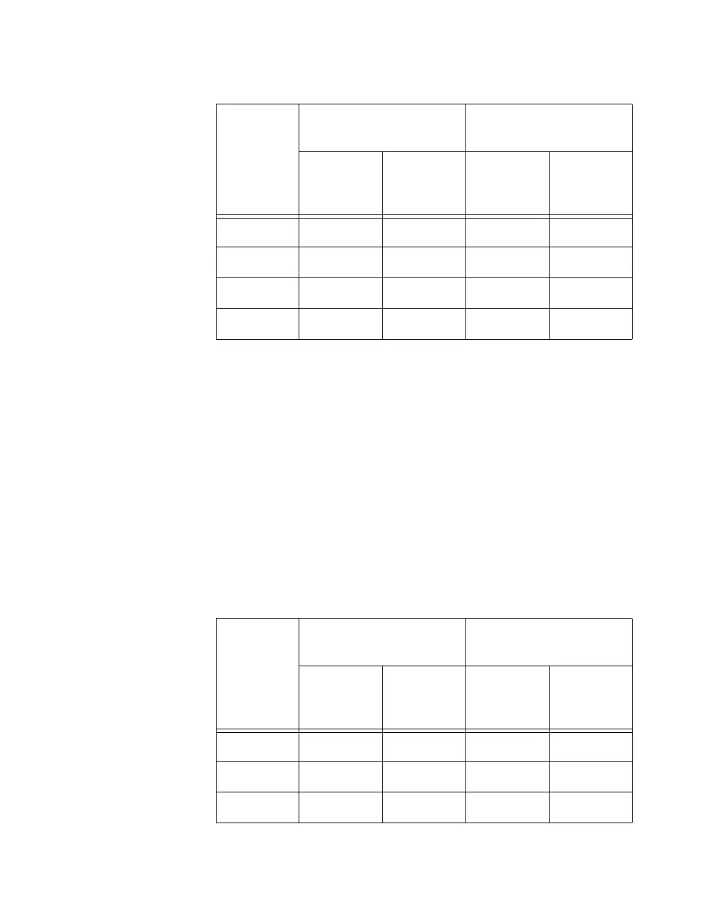
Table 3-7. SCXI-1120D Filter Jumper Allocation
Input
Channel
Number
First
Filter Jumper
Second
Filter Jumper
4.5 kHz
(Factory
Default)
22.5 kHz 22.5 kHz
4.5 kHz
(Factory
Default)
0 W17-A W17-B W25 W26
1 W18-A W18-B W27 W28
2 W19-A W19-B W29 W30
Table 3-6. SCXI-1120 Filter Jumper Allocation (Continued)
Input
Channel
Number
First
Filter Jumper
Second
Filter Jumper
4Hz
(Factory
Default)
10 kHz
4Hz
(Factory
Default)
10 kHz
 Loading...