VX150 TO VX2 TROUBLESHOOTING MANUAL RESPONDING TO ALARMS
VERSION 2.0 2023-04-20 PAGE 3.1.39
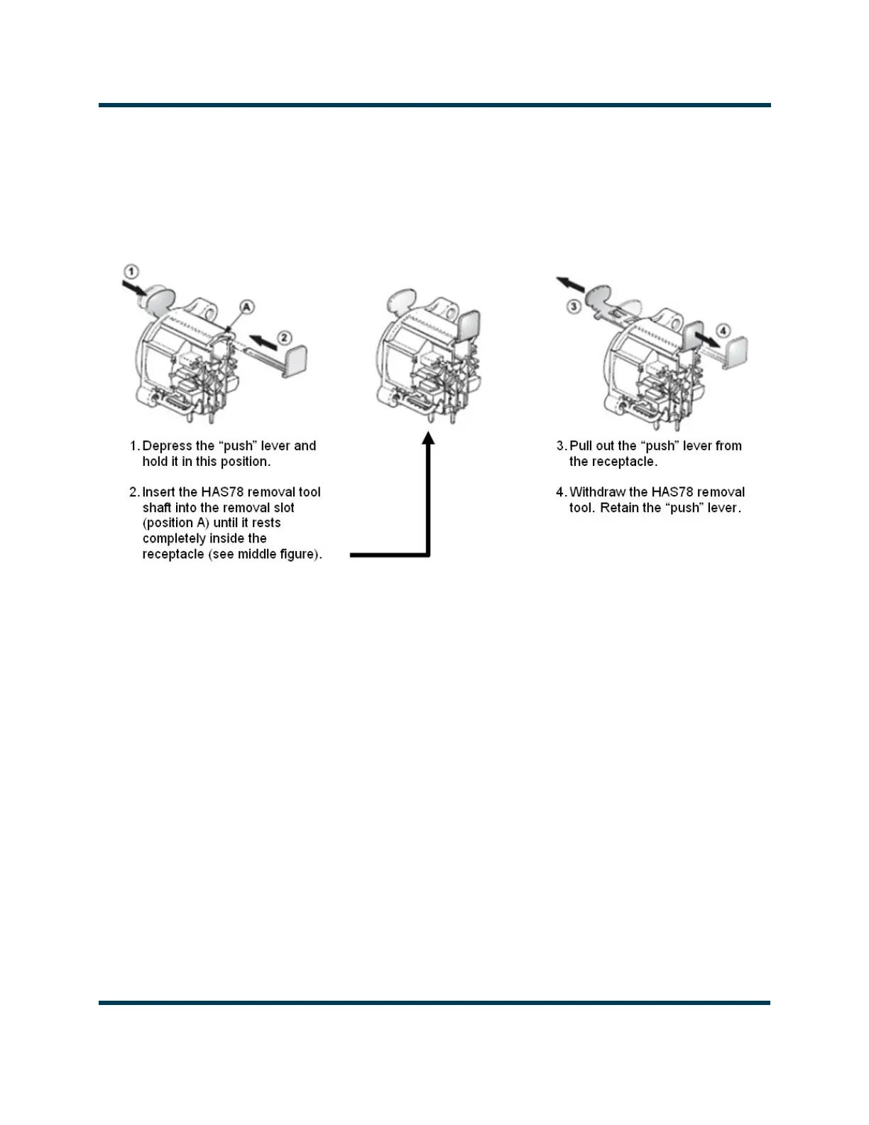
13. From the rear of the transmitter, remove and retain the two silver push button connector lock
(“push” lever) from the AES/EBU XLR connectors. Follow the manufacturer's instructions in
Figure 3.1.6 to remove the push button. You will need access to the front and rear of the receptacle
to remove it by pressing on the lock button while pressing the lock outwards from inside the
transmitter using the push lever removal tool (Nautel Part # HAS78, found in the ancillary kit).
Figure 3.1.6: XLR Connector Lock Removal
14. Remove and retain the four #4 screws securing the two XLR connectors.
15. Remove and retain the six M3 screws securing the Exciter PWB.
16. Slide the Exciter PWB towards the front of the transmitter and lift the Exciter PWB out.
17. Obtain a replacement Exciter PWB (Nautel part # NAPE90*).
18. Remove the Push Button Connector Locks from the new Exciter PWB (if present).
19. Install the Exciter PWB by reversing Step 4 to Step 16. Torque all hardware to 6 in-lbs (0.68 N-m).
20. Re-install the SD card retained in Step 5.
21. Install the Push Button Connector Locks into the XLR connectors.
22. Return the transmitter to operation.