VX150 TO VX2 TROUBLESHOOTING MANUAL RESPONDING TO ALARMS
PAGE 3.1.54 VERSION 2.0 2023-04-20
Front Panel User Interface (FPUI) Display Replacement
NOTE:
The USB provided with the transmitter contains videos (mp4 format) that support the
replacement procedures in this section. Go to the USB’s HOME screen and click VIDEOS. Videos for
replacing LRUs are listed in the Maintenance section.
See MD-1or MD-2 and MD-7 in the Mechanical Drawings section of this manual.
1. Turn RF off and disconnect ac power from the transmitter.
2. If applicable, remove and retain the four screws securing the transmitter in the rack.
3. Place on a suitable workbench.
4. Remove the PA Power Supply (U3) by pushing the panel latch to the right to unlock and slide
power supply out. Refer to Analog Audio PWB Replacement - see page 3.1.40.
5. Remove and retain the 21 M3 screws securing the top cover. Remove cover.
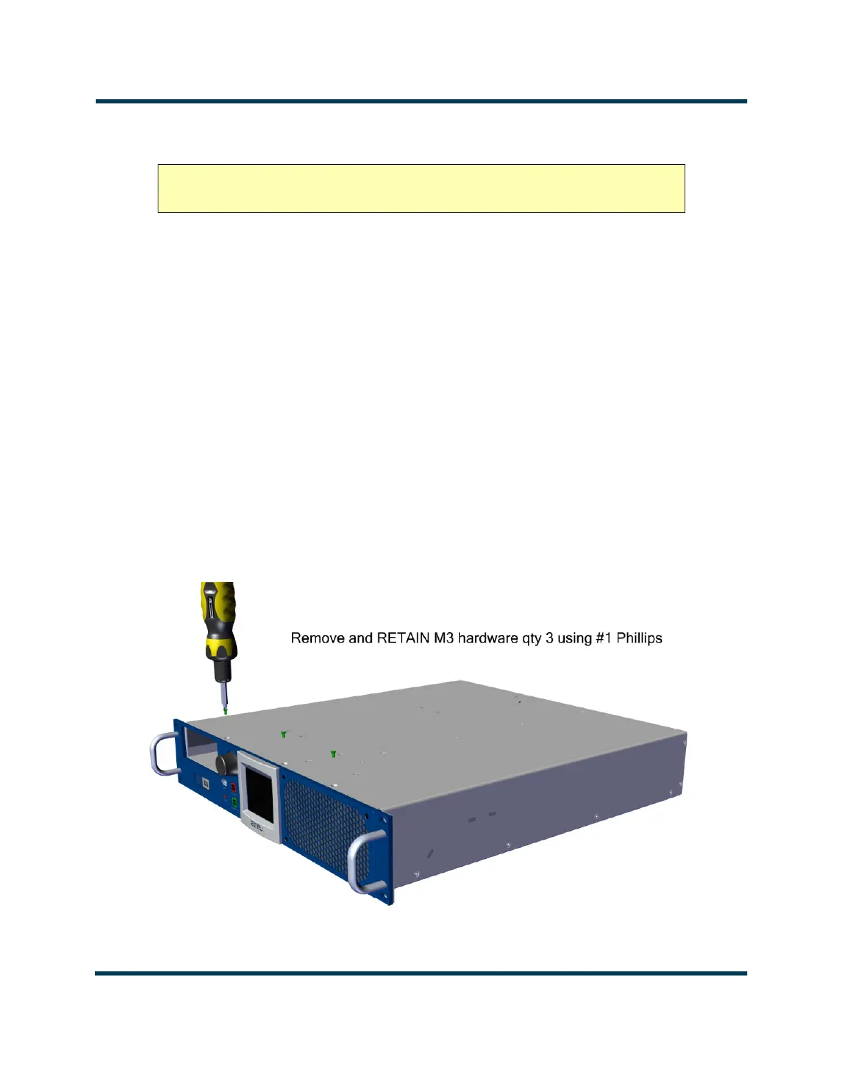
6. From the bottom of the transmitter, remove and retain the three M3 screws. See Figure 3.1.24.
Figure 3.1.24: M3 Screw Removal on bottom of Transmitter
CAUTION! The FPUI Display is static sensitive and must be handled in a static
protected manner.
 Loading...


