VX150 TO VX2 TROUBLESHOOTING MANUAL RESPONDING TO ALARMS
PAGE 3.1.60 VERSION 2.0 2023-04-20
Power Amplifier PWB Replacement
NOTE:
The USB provided with the transmitter contains videos (mp4 format) that support the
replacement procedures in this section. Go to the USB’s HOME screen and click VIDEOS. Videos for
replacing LRUs are listed in the Maintenance section.
See MD-1or MD-2 and MD-9 in the Mechanical Drawings section of this manual.
NOTE:
For VX1.5 /VX2 transmitters, refer to Mechanical Drawing MD-2 to determine the location of PA1
and PA2.
1. Turn RF off and disconnect ac power from the transmitter.
2. If applicable, remove and retain the four screws securing the transmitter in the rack.
3. Place the transmitter on a suitable workbench.
4. Remove and retain the 21 M3 screws securing the top cover. Remove cover.
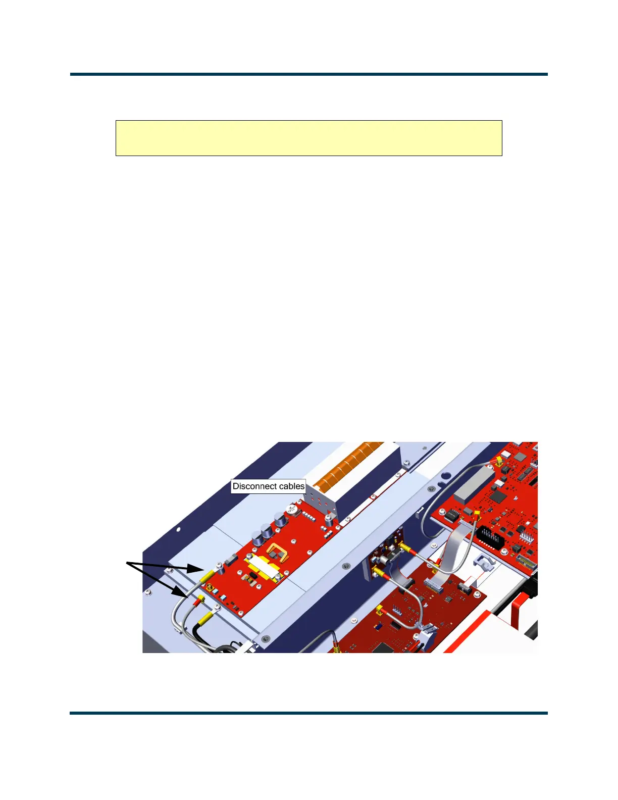
5. Disconnect the two cables connected to the PA (PA Volts from E1 and RF Drive from J1). Discard
the M3 screw attached to E1. See Figure 3.1.35.
Figure 3.1.35: PA Cable Removal
CAUTION! The Power Amplifier PWB is static sensitive and must be handled in a
static protected manner.