4-32
Upgrades and Options
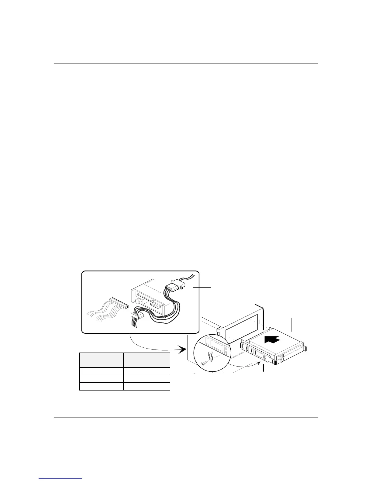
9. Locate and connect the power cable (Figure 4-16) to
the device; the connector is keyed and can be
inserted only one way.
Note: All power cables are labeled and must be
connected to the devices as shown in Figure 4-16.
10. Locate and connect the ribbon data cable (Figure 4-
16) to the device; the connector is keyed and can be
inserted only one way.
Note: If you are installing a SCSI device, be certain
to use the 50-pin internal SCSI data cable. This
cable comes from J36 on the system board to the
externally accessible bays and ends at the last SCSI
device. Do not confuse this cable with the 34-pin
diskette drive cable which begins on J12 of the
system board and ends at the diskette in bay D or
the 40-pin IDE drive cable which begins on J38 of
the system board and ends at the CD-ROM in bay A.
11. Ensure that the peripheral filler panel is removed
from the front panel.
12. Replace the front panel and side panel, and power on
the system.
Figure 4-16. Installing a Device into the System
5.25" Drive
Power Cable
DRIVE
LOCATION
POWER
CONNECTOR
A PS6
B PS7
C PS8