93
Appendix
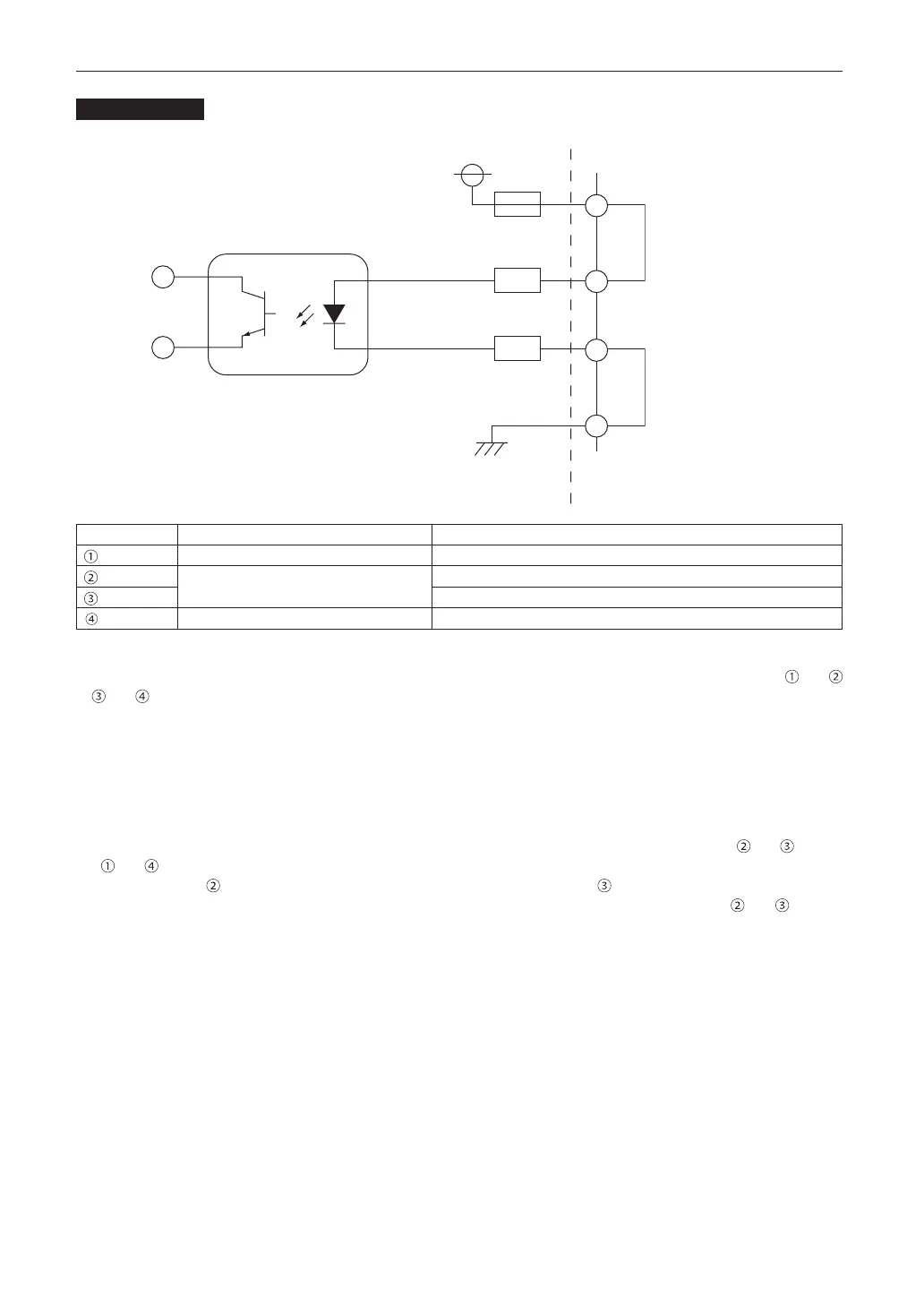
Circuit diagram
1
2
3
4
Photocoupler
VCC +5V
1A fuse
390Ω/0.5W resistor
390Ω/0.5W resistor
GND
Inside projector
Shorting wire 1
Shorting wire 2
Interlock connector
Connector no. Photocoupler ON/OFF Description
— +5V supply
ON/OFF Connects to the photocoupler anode inside the projector
Connects to the photocoupler cathode inside the projector
— Ground
• Whenthelengthofthewiringislessthan5m(approximate)
Remove shorting wire 1 or shorting wire 2 and connect the external contacts (switch) to the projector interlock terminal ( and
or and ) by cable.
- The projector operates normally when the contacts are closed and the system shuts off when the contacts are open.
- A power supply external from the projector is not necessary.
- A maximum of 2 sets of external contacts can be connected. If you are only using a single set of external contacts, connect-
ing the shorting wire to the interlock terminal you are not using.
- The minimum rating required of the external contacts is 2mA.
• Whenthelengthofthewiringisatleast5m(approximate)
Remove shorting wire 1 and shorting wire 2 and connect the external device to the projector interlock terminals ( and ) (do not
use and ).
- Connect terminal to the positive side of the external device and connect terminal to the negative side.
- The projector operates normally when a voltage in the range of DC5 to 16V is applied between terminals and , and the
system shuts off when the voltage is 0V.
- The minimum rated current required of the external device varies depending on the voltage applied between the terminals by
the external device.
- When feeding the cable out from the projector, feed it so that it passes through the hole on the front face of the projector.