ROI-S04488 OPERATION
3-5
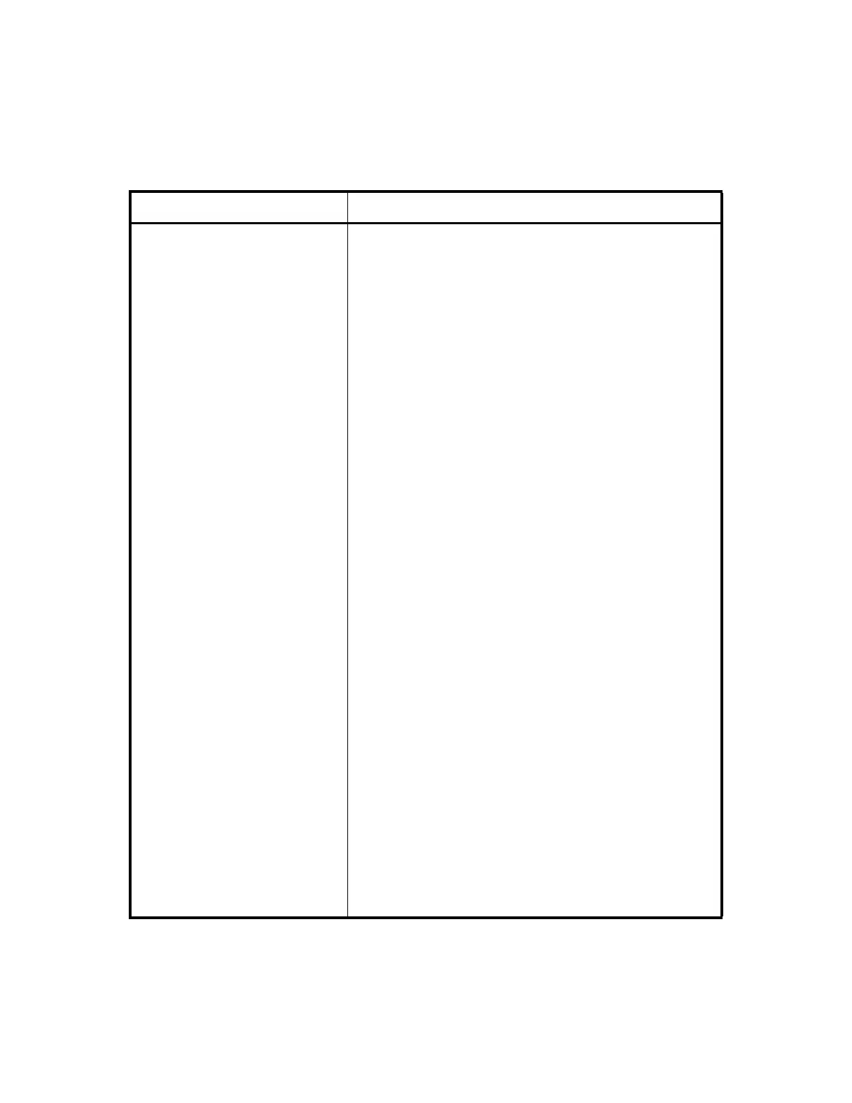
OW/DSC/ASC
(D-sub Connector, 25 Pins)
Engineering orderwire (EOW), digital service channel (DSC),
analog service channel (ASC) and ALARM signal input/
output
Pins 1 (+) and 2 (−)/
Pins 1 and 2*
2
ASC1 input (VF) (optional) or Alarm1*
2
input (optional)
Notes: 1. *
2
Applies to the ALM INTFC module.
2. Cluster Alarm 1 input (photocoupler)
Normal signal in : Open
Alarm signal in : Closed
Pins 3 (+) and 4 (−)/
Pins 3 and 4*
2
ASC2 input (VF) (optional) or Alarm2*
2
input (optional)
Notes: 1. *
2
Applies to the ALM INTFC module.
2. Cluster Alarm 2 input (photocoupler)
Normal signal in : Open
Alarm signal in : Closed
Pins 5 (+) and 6 (−) EOW input (VF)
Pins 7 (+) and 8 (−)
64 kHz clock input*
1
Pins 9 (+) and 10 (−)
DSC1 input (RS-232C, 64K (G.703)*
1
or 64K (V.11)*
1
)
Pins 11 (+) and 12 (−) DSC2 input (RS-232C, RS-422 or RS-485)
Pins 14 (+) and 15 (−)/
Pins 14 and 15*
2
ASC1 output (VF) (optional) or Alarm1*
2
output (optional)
Notes: 1. *
2
Applies to the ALM INTFC module.
2. Cluster Alarm 1 output (relay contact)
Normal signal out : Open
Alarm signal out : Closed
Pins 16 (+) and 17 (−)/
Pins 16 and 17*
2
ASC2 output (VF) (optional) or Alarm2*
2
output (optional)
Notes: 1. *
2
Applies to the ALM INTFC module.
2. Cluster Alarm 2 output (relay contact)
Normal signal out : Open
Alarm signal out : Closed
Pins 18 (+) and 19 (−) EOW output (VF)
Pins 20 (+) and 21 (−)
64 kHz clock output*
1
Pins 22 (+) and 23 (−)
DSC1 output (RS-232C, 64K (G.703)*
1
or 64K (V.11)*
1
)
Pins 24 (+) and 25 (−) DSC2 output (RS-232C, RS-422 or RS-485)
Table 3-1 Interface Terminals and Jacks in 1+0 system (3/8)
Terminal Description