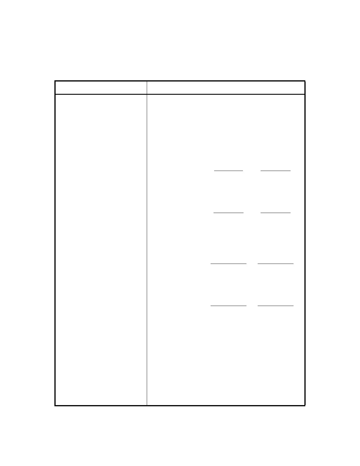
OPERATION ROI-S04488
3-6
Pin 13 Ground
Notes:1. *
1
Optional
2. Both ASC and DSC 64K cannot be used
simultaneously.
ALM/AUX ALM
(D-sub Connector, 37 Pins)
Alarm and transmission network surveillance auxiliary alarm
input/output
Pins 1 (COM), 2 (NO) and
3 (NC)
Transmitter alarm output*
3
Between Between
Pins 1 and 2
Pins 1 and 3
Normal state : Open Closed
Alarm state : Closed Open
Pins 4 (COM), 5 (NO) and
6 (NC)
Receiver alarm output*
3
Between Between
Pins 4 and 5
Pins 4 and 6
Normal state : Open Closed
Alarm state : Closed Open
Pins 20 (COM), 21 (NO)
and 22 (NC)
BER alarm output when BER worse than 10
-6
/10
-5
/10
-4
/10
-3
(selectable)*
3
Between Between
Pins 20 and 21
Pins 20 and 22
Normal state : Open Closed
Alarm state : Closed Open
Pins 23 (COM), 24 (NO)
and 25 (NC)
Maintenance alarm output*
3
Between Between
Pins 23 and 24
Pins 23 and 25
Normal state : Open Closed
Alarm state : Closed Open
Note:*
3
The BER threshold values and alarm items are set
in factory (default). To change the setting of alarm
items by the PC, refer to Section 3.4.1 “Alarm
Table” of this Manual.
(Housekeeping alarm input through optional PM CARD.)
Pin 7 Input 11
Pin 8 (G) Input 12
Pin 9 Input 21
Table 3-1 Interface Terminals and Jacks in 1+0 system (4/8)
Terminal Description