UX5000 Issue 1.0
Multimedia Conference Bridge Installation Manual 2 - 3
___________________________________________________________________________________
___________________________________________________________________________________
SECTION 2INDICATORS, SWITCHES AND CONNECTORS
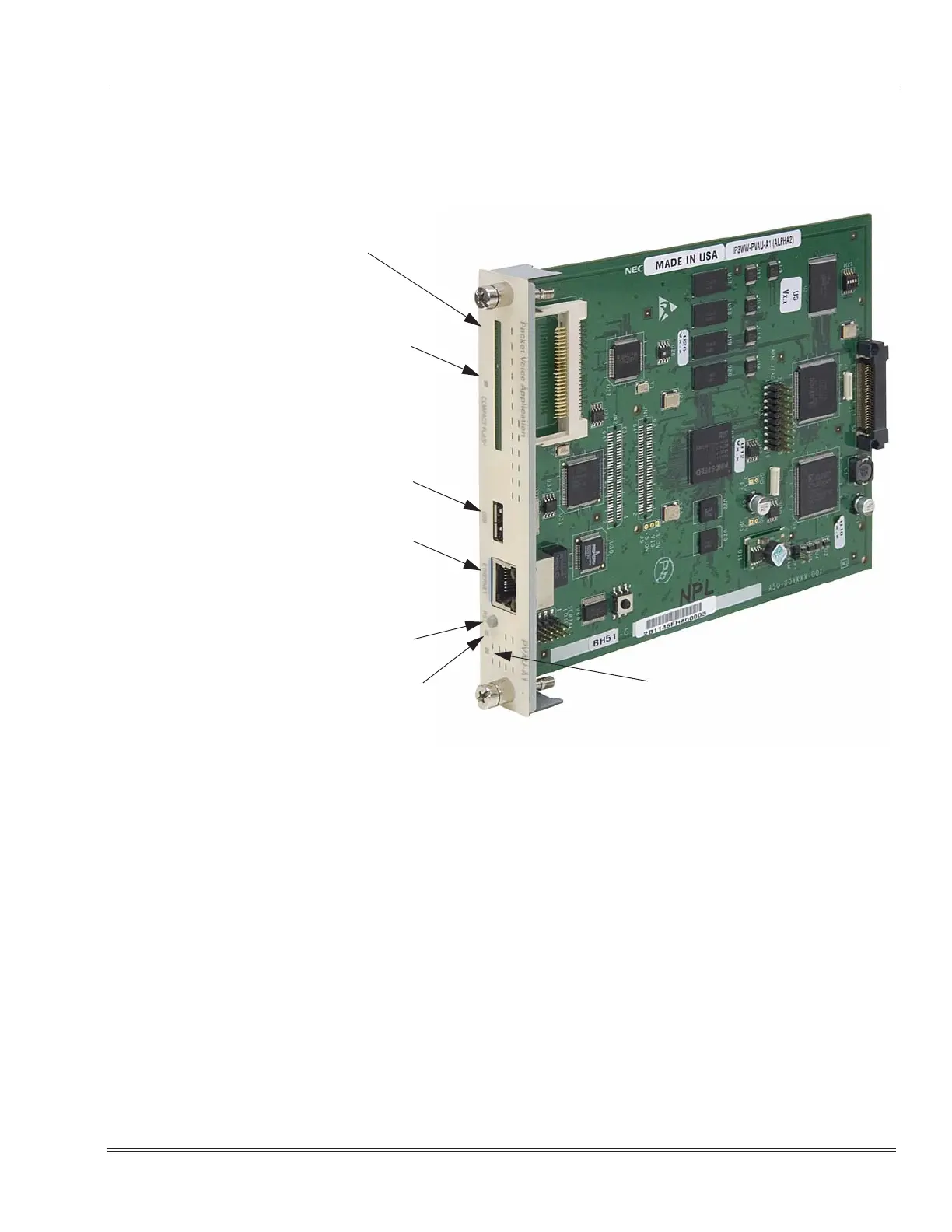
Refer to Figure 2-1 PVAU for LED and switch locations.
2.1 Switches
The Multimedia Conference Bridge Application has the following switches.
DIP Switch SW1
Reserved for future use.
RESET Switch SW3
This switch allows the technician to reset the Multimedia Conference
Bridge Application blade without having to remove and insert it again in
the UX5000 chassis.
Figure 2-1 PVAU
CompactFlash (CF)
RJ45 Ethernet Connection
(Gren: Data
Yellow: Connectivity)
Reset Button (RST)
USB Connection
LED
(Red: Reading)
Busy LED
(ON: In Use
Live LED
(Status LED)

 Loading...


