E-PAK 500EN
22
4.3 Technical and electrical data
4.3.1 Technical data
‘Table 4-1: Technical data’ contains technical data for E-PAK 500.
Figure 20 shows the fan characteristics diagram.
Table 4-1: Technical data
E-PAK 500
Operatingairowat15kPa 500 m³/h (942 cfm)
Mainlterarea 3.4 m² (36.6 sqft)
Mainltermaterial Polyester
Ambient temperature
-10–+40 °C (14–104 °F)
Process air temperature 0–60 °C (32–102 °F)
Compressed air:
• requirements 6–10 bar (87–145 PSI)
• consumption 0.5 NL (0.13 gal)/cleaning pulse
Dimension, inlet Ø 100 mm (3.937 in)
Dimension, outlet Ø 105 mm (4.13 in)
Collector volume 50 litres (13.21 gal)
Weight 360 kg (794 lb)
Dimensions See Section ‘4.2 Dimensions’
Material recycling Approximately95percentperweight
Sound level <70 dB(A)
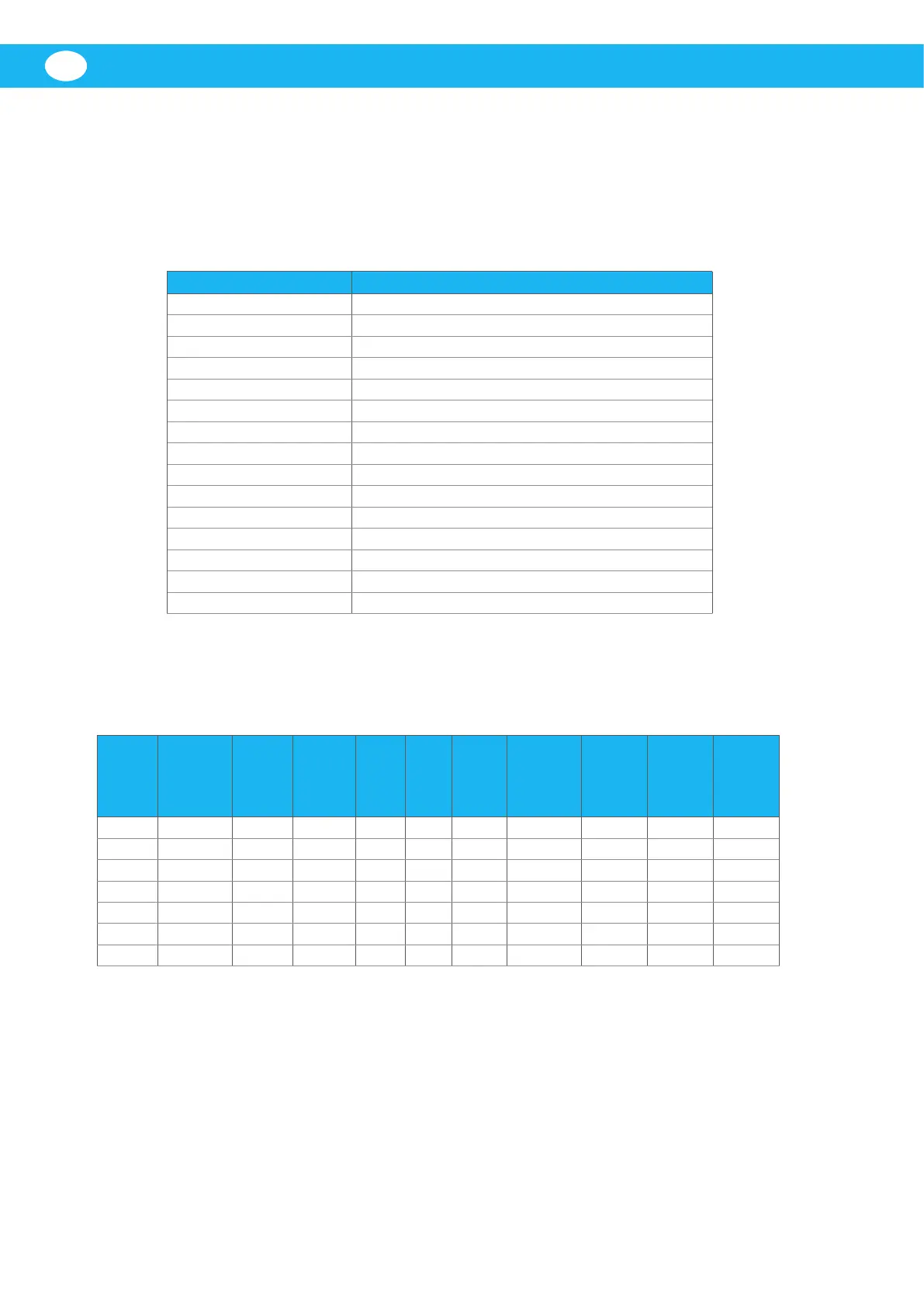
4.3.2 Electrical data
‘Table 4-2: Electrical data’ contains electrical data for E-PAK 500. For the location of the motor
and starter cable areas (items Z, V and X in the table), see Figure 17.
Table 4-2: Electrical data
Motor
power
(kW/hp)
Voltage
and
frequency
(V)/(Hz)
Nom.
current
(A)
F1
Recom.
mains
fuses,
slow (A)
F2 &
F3,
slow
(A)
F4,
slow
(A)
F5 &
F6,
fast
(A)
S1F Over-
load relay
setting
(A)
Min.
cable
area to
motor
(mm
2
) Z
Cable
area
inside
starter
(mm
2
) V
Cable
area
inside
starter
(mm
2
) X
12.5 230/50 47.5 50 6 4 1 27.4 6.0 2.5 16.0
13 400/50 27 35 6 4 1 15.6 2.5 2.5 6.0
15.3/20 208/60 55.0 60 6 4 1 31.8 6.0 4.0 16.0
14.5/19 230/60 49.6 60 6 4 1 28.6 6.0 4.0 16.0
15.3/20 440/60 27 35 6 4 1 15.6 2.5 2.5 10.0
15.3/20 460/60 26.0 35 6 4 1 15.0 2.5 2.5 10.0
15.3/20 575/60 20.4 25 6 4 1 11.8 2.5 2.5 10.0
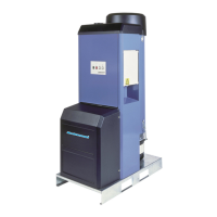
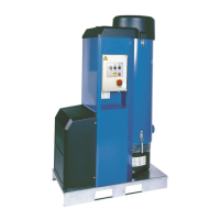
5 Main components
Figure 4 shows the main components of E-PAK 500. These are as follows:
1. Filter cleaning device.
2. Start and control unit with control panel.
3. Dust collector.
4. Vacuum limiting valve.
5. Thermal switch, 125 °C (257 °F), with automatic reset.
 Loading...