Hangzhou NeoDen Technology Co.,Ltd.
We can move down-looking camera or nozzle 1 and nozzle 6, find corresponding component
and confirm the component center coordinate, after clicking “save”, go back to main page,
then input related component information (Notice: name refer to component bit number,
specification refer to component value, footprint refer to common footprint name. Like
0603,0805,1206 etc. The angle is based on the placement direction of component on the circuit
board to confirm, transverse is 0 degree or 180 degree, vertical is 90 degree or negative 90
degree, which is mainly based on the polarity of component, degree must be integer degree;)
after all parameter setting, the first component information has been finished; click the “new”
in next step, the component list will add a row, coordinate information will entirely copy
adjacent up row, then click “align” to find the next component center, ensure to modify, reedit
name, specification, footprint, angle and etc., after finish it, continue to reedit until all edit
finish.
●Component movement
During the process of edit, sometimes, need to do a slightly adjustment for the edited file, we
have three types
(1) move up: The main thing is to move the selected components upward
(2) move down: The main thing is to move the selected components downward
(3) move to head position: The main thing is to move the selected components to the head
position to place.
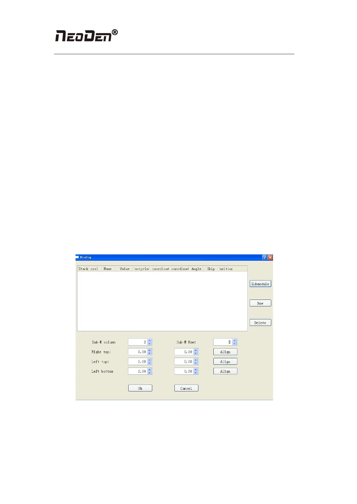
●Batch generate component
Figure (2.1.3.2-3)
Some circuit board is relatively regular and easy in actual edit, as for this type circuit board,
we can through mass production to generate coordinate file, the PCB as shown in figure
(2.1.3.2-3), we can see that it has a rectangular region and a circular region together to form a
small panel. We call this compositive panel as submodule. We can generate this small
imposition through submodule generation. We find it is consisting of 2 rows and 2 column,