N58 Hardware User Guide
Chapter 2 About N58
Copyright © Neoway Technology Co., Ltd. All rights reserved.
GNSS
1)
indicates that the configuration is optional.
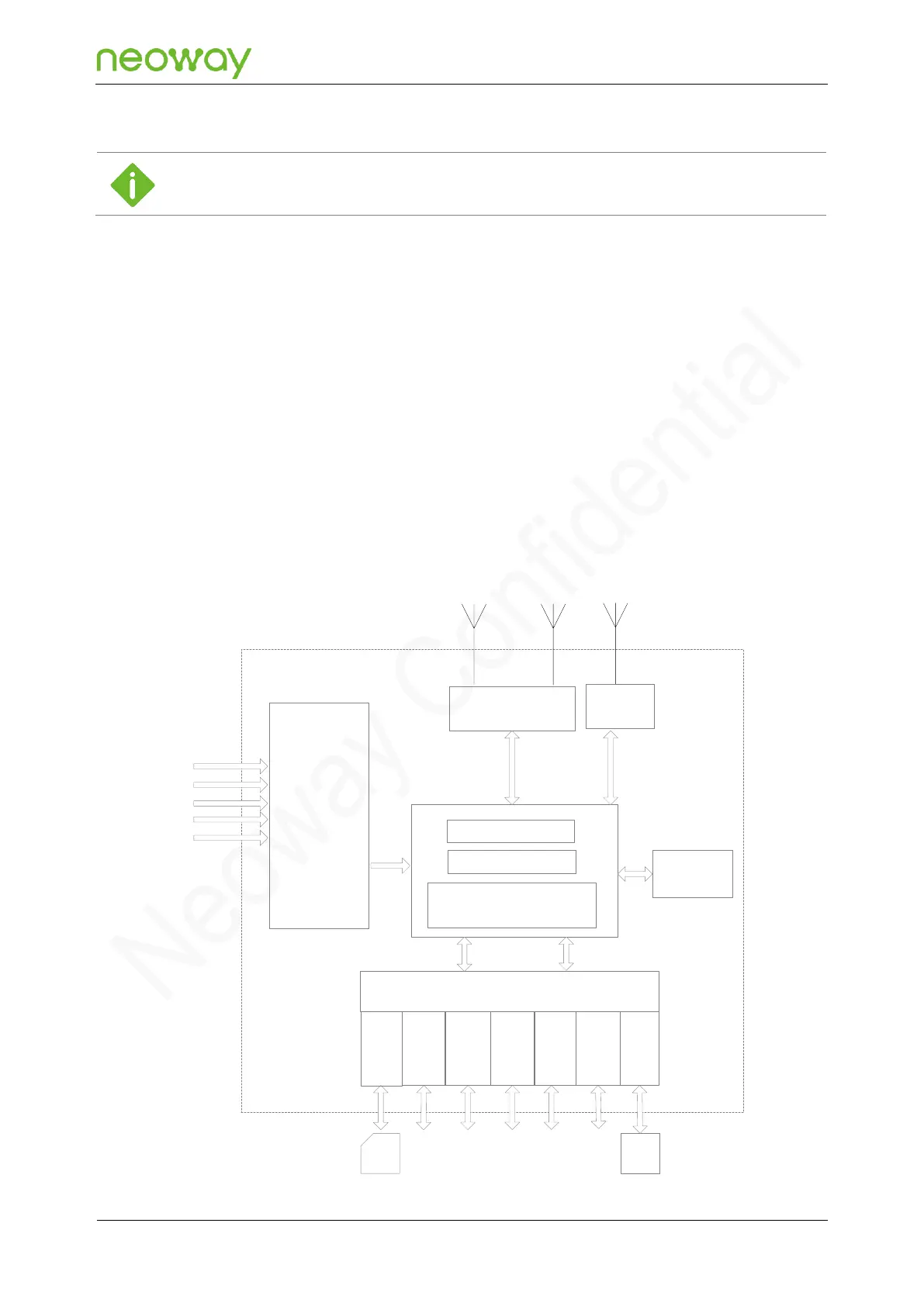
2.2 Block Diagram
N58 consists of the following functional units:
Baseband chip unit
26 MHz crystal
Power manager
RF functional unit
Digital interfaces (including USIM, I2C, SPI, KEYPAD, UART, USB, and SDIO)
Analog interfaces (ADC, MIC, and SPK)
Figure 2-1 Block diagram
VBAT
Power
manager
26 MHz
crystal
RF front-end
I2C
Digital interface
USBUART
USIM
PC
ANT_MAIN ANT_BT ANT_GNSS
PWRKEY_N
RESET
KEYP
ADUSIM
SPI SDIO
MIC, SPK
GNSS
ADC
RF transceiver
Baseband
NOR flash (64 Mb) +
PSRAM (128 Mb)