N58 Hardware User Guide
Chapter 5 Application Interfaces
Copyright © Neoway Technology Co., Ltd. All rights reserved.
Connect a resistor with a resistance not greater than 20 Ω respectively to USIM_DATA,
USIM_RESET, USIM_CLK, and USIM_DET in series close to the module to enhance the ESD
performance.
The N58 module supports USIM card detection. USIM_DET is a 1.8 V interruption pin. The
circuit design of interruption detection is determined by the structure of the USIM card connector.
The principle is that the levels of the detection pin are inverted before and after a USIM card is
inserted. In Figure 5-23, the reference design circuit is assuming that USIM_DET is floating
before a USIM card is inserted and is pulled up to 1.8 V after a USIM card is inserted. High level
means USIM card detected while low level means no USIM card detected.
If the user USIM card does not use the hot plug function, the USIM_DET pin of the N58 module must be pulled
up to 1.8 V by using a 47 kΩ resistor in series, and the software must disable the USIM hot plug detection
function. Figure 5-24 shows the reference design of USIM card (without the hot plug function) interfaces.
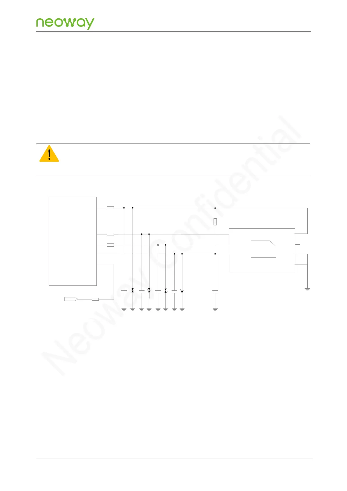
Figure 5-24 Reference design of USIM card (without the hot plug function) interfaces
1uF
CLK
RST
VCC
VPP
GND
USIM Card
DATA
GND
USIM_DATA
USIM_
CLK
USIM_RESET
USIM_
VCC
USIM_ DET
N58 Module
4.7kΩ
C1
R5
C2 C3
C4
C5
D1
20Ω
R1
20Ω
R2
20Ω
R3
D2 D3 D4
47kΩ
VDD_1P8
R4
PCB design guidelines:
RF radiation easily interferes with the USIM card and its signal cables, causing the USIM card to
fail to work properly. Place the USIM card far away from the antenna area and RF circuit area.
Place the USIM card close to the module, and USIM traces should be as short as possible.
Place the series resistance and ESD protection components on USIM signal cables to be close
to the USIM card.
Surround USIM signal cable traces with ground to enhance the anti-interference capability.