N58 Hardware User Guide
Chapter 5 Application Interfaces
Copyright © Neoway Technology Co., Ltd. All rights reserved.
5.6.8 Keypad
N58 supports matrix keyboard (4x3: 4 rows and 3 columns). The following table provides the
description of keypad pins.
Leave this pin floating if it is not used.
Leave this pin floating if it is not used.
Leave this pin floating if it is not used.
Leave this pin floating if it is not used.
Leave this pin floating if it is not used.
Leave this pin floating if it is not used.
Leave this pin floating if it is not used.
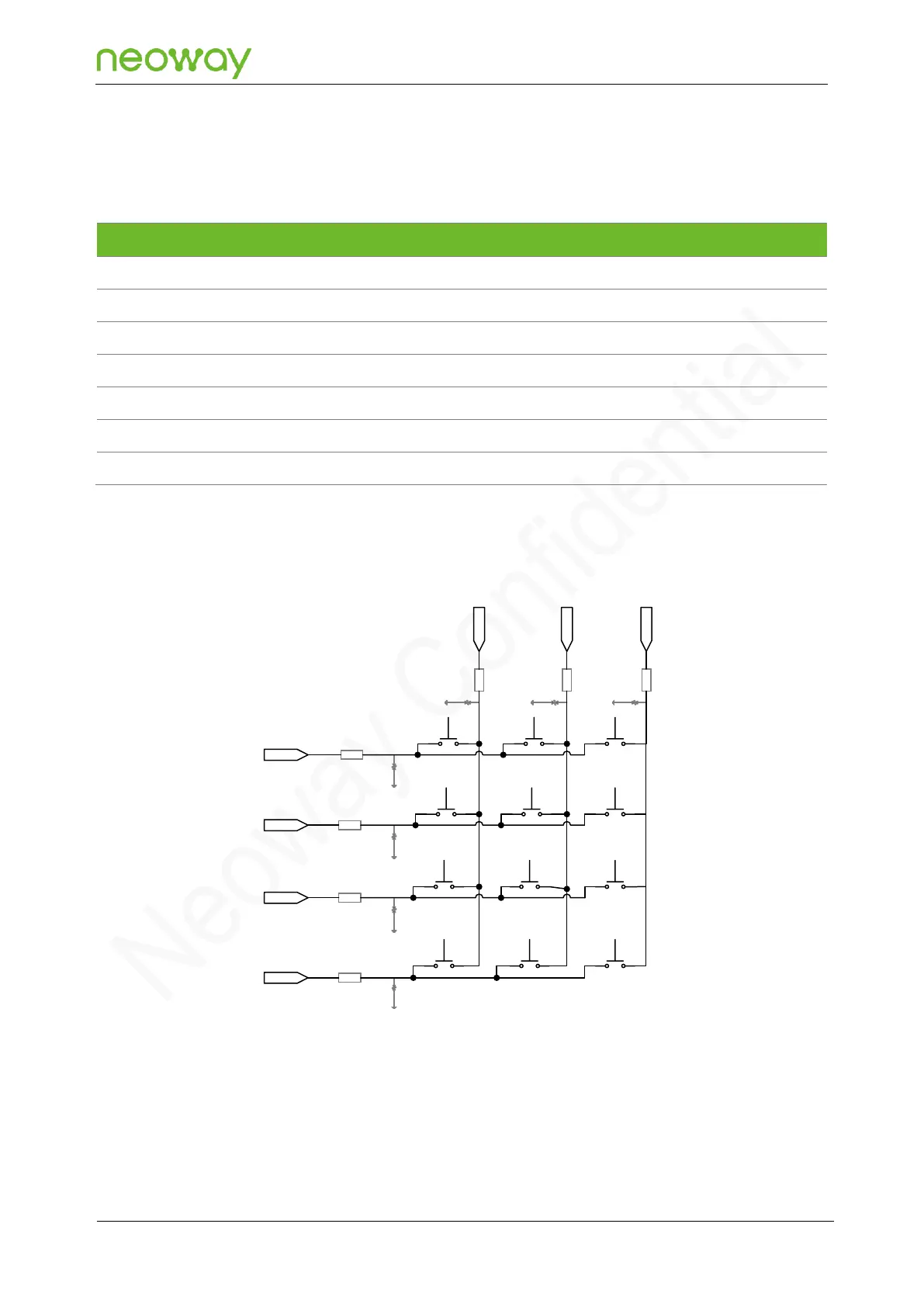
Figure 5-36 Keypad reference design
1kΩ
1kΩ
1kΩ
1kΩ
1kΩ 1kΩ 1kΩ
KEYOUT0
KEYOUT1
KEYOUT2
KEYOUT3
KEYIN
1
KEYIN
2
KEYIN
3
Schematic design guidelines:
To improve the ESD performance of the keypad interface, an ESD protection component must be
added to the keypad interface, and a 1 kΩ resistor must be connected in series with the signal cable.